- Introduction to the Relational Model
- Integrity Constraints over Relations
- Enforcing Integrity Constraints
- Logical Database Design: ER to Relational
- Introduction to Views
The relational model is very simple and elegant: a database is a collection of one or more relations, where each relation is a table with rows and columns. This simple tabular representation enables even novice users to understand the contents of a database, and it permits the use of simple, high-level languages to query the data. The major advantages of the relational model over the older data models are its simple data representation and the ease with which even complex queries can be expressed.
Introduction to the Relational Model
The main construct for representing data in the relational model is a relation. A relation consists of a relation schema and a relation instance. The relation instance is a table, and the relation schema describes the column heads for the table. The schema specifies the relation’s name, the name of each field (or column, or attribute), and the domain of each field. A domain is referred to in a relation schema by the domain name and has a set of associated values.
For example, as the following schema shows:
Students(sid: string, name: string, login: string,
        age: integer, gpa: real)
This says, for instance, that the field named sid has a domain named string. The set of values associated with domain string is the set of all character strings.
We now turn to the instances of a relation. An instance of a relation is a set of tuples, also called records, in which each tuple has the same number of fields as the relation schema. A relation instance can be thought of as a table in which each tuple is a row, and all rows have the same number of fields. (The term relation instance is often abbreviated to just relation, when there is no confusion with other aspects of a relation such as its schema.)
An instance of the Students relation appears in Figure 3.1. The instance 81 contains six tuples and has, as we expect from the schema, five fields. Note that no two rows are identical. This is a requirement of the relational model-each relation is defined to be a set of unique tuples or rows.
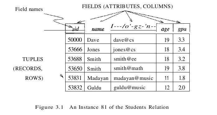
The degree, also called arity, of a relation is the number of fields. The cardinality of a relation instance is the number of tuples in it. In Figure 3.1, the degree of the relation (the number of columns) is five, and the cardinality of this instance is six.
The SQL language standard uses the word table to denote relation. The subset of SQL that supports the creation, deletion, and modification of tables is called the Data Definition Language (DDL).
Integrity Constraints over Relations
A database is only as good as the information stored in it, and a DBMS must therefore help prevent the entry of incorrect information. An integrity constraint (IC) is a condition specified on a database schema and restricts the data that can be stored in an instance of the database. If a database instance satisfies all the integrity constraints specified on the database schema, it is a legal instance. A DBMS enforces integrity constraints, in that it permits only legal instances to be stored in the database.
Key Constraints
Consider the Students relation and the constraint that no two students have the same student id. This IC is an example of a key constraint. A key constraint is a statement that a certain minimal subset of the fields of a relation is a unique identifier for a tuple. A set of fields that uniquely identifies a tuple according to a key constraint is called a candidate key for the relation; we often abbreviate this to just key. In the case of the Students relation, the (set of fields containing just the) sid field is a candidate key.
Let us take a closer look at the above definition of a (candidate) key. There are two parts to the definition:
- Two distinct tuples in a legal instance (an instance that satisfies all ICs, including the key constraint) cannot have identical values in all the fields of a key.
- No subset of the set of fields in a key is a unique identifier for a tuple.
The first part of the definition means that, in any legal instance, the values in the key fields uniquely identify a tuple in the instance. For example, several students may have the same name, although each student has a unique student id. If the name field is declared to be a key, the DBMS will not allow the Students relation to contain two tuples describing different students with the same name.
The second part of the definition means, for example, that the set of fields {sid, name} is not a key for Students, because this set properly contains the key {sid}. The set {sid, name} is an example of a superkey, which is a set of fields that contains a key.
Note that every relation is guaranteed to have a key. Since a relation is a set of tuples, the set of all fields is always a superkey. If other constraints hold, some subset of the fields may form a key, but if not, the set of all fields is a key.
A relation may have several candidate keys. For example, the login and age fields of the Students relation may, taken together, also identify students uniquely. That is, {login, age} is also a key. It may seem that login is a key, since no two rows in the example instance have the same login value. However, the key must identify tuples uniquely in all possible legal instances of the relation. By stating that {login, age} is a key, the user is declaring that two students may have the same login or age, but not both.
Out of all the available candidate keys, a database designer can identify a primary key. Intuitively, a tuple can be referred to from elsewhere in the database by storing the values of its primary key fields. For example, we can refer to a Students tuple by storing its sid value. As a consequence of referring to student tuples in this manner, tuples are frequently accessed by specifying their sid value. In principle, we can use any key, not just the primary key, to refer to a tuple. However, using the primary key is preferable because it is what the DBMS expects this is the significance of designating a particular candidate key as a primary key and optimizes for. For example, the DBMS may create an index with the primary key fields as the search key, to make the retrieval of a tuple given its primary key value efficient.
In SQL, we can declare that a subset of the columns of a table constitute a key by using the UNIQUE constraint. At most one of these candidate keys can be declared to be a primary key, using the PRIMARY KEY constraint. (SQL does not require that such constraints be declared for a table.) Let us revisit our example table definition and specify key information:
CREATE TABLE Students ( sid CHAR(20) ,
                        name CHAR (30) ,
                        login CHAR(20) ,
                        age INTEGER,
                        gpa REAL,
                        UNIQUE (name, age),
                        CONSTRAINT StudentsKey PRIMARY KEY (sid) )
This definition says that sid is the primary key and the combination of name and age is also a key. The definition of the primary key also illustrates how we can name a constraint by preceding it with CONSTRAINT constraint-name. If the constraint is violated, the constraint name is returned and can be used to identify the error.
Foreign Key Constraints
Sometimes the information stored in a relation is linked to the information stored in another relation. If one of the relations is modified, the other must be checked, and perhaps modified, to keep the data consistent. An IC involving both relations must be specified if a DBMS is to make such checks. The most common IC involving two relations is a foreign key constraint.
Suppose that, in addition to Students, we have a second relation:
Enrolled(studid: string, cid: string, grade: string)
To ensure that only bona fide students can enroll in courses, any value that appears in the studid field of an instance of the Enrolled relation should also appear in the sid field of some tuple in the Students relation. The studid field of Enrolled is called a foreign key and refers to Students. The foreign key in the referencing relation (Enrolled, in our example) must match the primary key of the referenced relation (Students, in our example). That is, it must have the same number of columns and compatible data types, although the column names can be different. This constraint is illustrated in Figure 3.4. As the figure shows, there may well be some Students tuples that are not referenced from Enrolled (e.g., the student with sid=50000). However, every studid value that appears in the instance of the Enrolled table appears in the primary key column of a row in the Students table.

If we try to insert the tuple (55555, Artl04, A) into Enrolled, the IC is violated because there is no tuple in Students with sid 55555; the database system should reject such an insertion. Similarly, if we delete the tuple (53666, Jones, jones@cs, 18, 3.4) from Students, we violate the foreign key constraint because the tuple (53666, Historyl05, B) in Enrolled contains studid value 53666, the sid of the deleted Students tuple. The DBMS should disallow the deletion or, perhaps, also delete the Enrolled tuple that refers to the deleted Students tuple.
Let us define Enrolled(studid: string, cid: string, grade: string):
CREATE TABLE Enrolled ( studid CHAR(20) ,
                        cid CHAR(20),
                        grade CHAR(10),
                        PRIMARY KEY (studid, cid),
                        FOREIGN KEY (studid) REFERENCES Students)
Enforcing Integrity Constraints
The impact of foreign key constraints is more complex because SQL sometimes tries to rectify a foreign key constraint violation instead of simply rejecting the change. We discuss the referential integrity enforcement steps taken by the DBMS in terms of our Enrolled and Students tables, with the foreign key constraint that Enrolled.sid is a reference to (the primary key of) Students. Consider the instance of Enrolled shown in Figure 3.4. Deletions of Enrolled tuples do not violate referential integrity, but insertions of Enrolled tuples could. The following insertion is illegal because there is no Students tuple with sid 51111:
INSERT
INTO Enrolled (cid, grade, studid)
VALUES ('Hindi101', 'B', 51111)
On the other hand, insertions of Students tuples do not violate referential integrity, and deletions of Students tuples could cause violations. Further, updates on either Enrolled or Students that change the studid (respectively, sid) value could potentially violate referential integrity.
SQL provides several alternative ways to handle foreign key violations. We must consider three basic questions:
- What should we do if an Enrolled row is inserted, with a studid column value that does not appear in any row of the Students table? In this case, the INSERT command is simply rejected.
- What should we do if a Students row is deleted? The options are:
- Delete all Enrolled rows that refer to the deleted Students row.
- Disallow the deletion of the Students row if an Enrolled row refers to it.
- Set the studid column to the sid of some (existing) ‘default’ student, for every Enrolled row that refers to the deleted Students row.
- For every Enrolled row that refers to it, set the studid column to null. In our example, this option conflicts with the fact that stud’id is part of the primary key of Enrolled and therefore cannot be set to null. Therefore, we are limited to the first three options in our example, although this fourth option (setting the foreign key to null) is available in general.
- What should we do if the primary key value of a Students row is updated? The options here are similar to the previous case.
Transactions and Constraints
A program that runs against a database is called a transaction, and it can contain several statements (queries, inserts, updates, etc.) that access the database. By default, a constraint is checked at the end of every SQL statement that could lead to a violation, and if there is a violation, the statement is rejected. Sometimes this approach is too inflexible.
SQL allows a constraint to be in DEFERRED or IMMEDIATE mode. A constraint in deferred mode is checked at commit time. In our example, the foreign key constraints on Boats and Sailors can both be declared to be in deferred mode. “VVe can then insert? boat with a nonexistent sailor as the captain (temporarily making the database inconsistent), insert the sailor (restoring consistency), then commit and check that both constraints are satisfied.
Logical Database Design: ER to Relational
Entity Sets to Tables
An entity set is mapped to a relation in a straightforward way: Each attribute of the entity set becomes an attribute of the table. Note that we know both the domain of each attribute and the (primary) key of an entity set.
Relationship Sets (without Constraints) to Tables
We begin by considering relationship sets without key and participation constraints. To represent a relationship, we must be able to identify each participating entity and give values to the descriptive attributes of the relationship. Thus, the attributes of the relation include:
- The primary key attributes of each participating entity set, as foreign key fields.
- The descriptive attributes of the relationship set.
Consider the Works_In2 relationship set shown in Figure 3.10. Each department has offices in several locations and we want to record the locations at which each employee works.
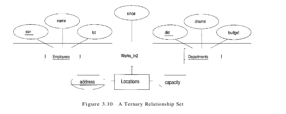
All the available information about the Works_In2 table is captured by the following SQL definition:
CREATE TABLE Works_In2 ( ssn CHAR(11),
                        did INTEGER,
                        address CHAR(20) ,
                        since DATE,
                        PRIMARY KEY (ssn, did, address),
                        FOREIGN KEY (ssn) REFERENCES Employees,
                        FOREIGN KEY (address) REFERENCES Locations,
                        FOREIGN KEY (did) REFERENCES Departments)
Note that the address, did. and ssn fields cannot take on null values. Because these fields are part of the primary key for Works_In2, a NOT NULL constraint is implicit for each of these fields.
Translating Relationship Sets with Key Constraints
If a relationship set involves n entity sets and some m of them are linked via arrows in the ER diagram, the key for anyone of these m entity sets constitutes a key for the relation to which the relationship set is mapped. Hence we have m candidate keys, and one of these should be designated as the primary key.
Consider the relationship set Manages shown in Figure 3.12. The table corresponding to Manages has the attributes ssn, did, since. However, because each department has at most one manager, no two tuples can have the same did value but differ on the ssn value. A consequence of this observation is that did is itself a key for Manages; indeed, the set did, ssn is not a key (because it is not minimal). The Manages relation can be defined using the following SQL statement:
CREATE TABLE Manages (ssn CHAR ( 11) ,
                did INTEGER,
                since DATE,
                PRIMARY KEY (did),
                FOREIGN KEY (ssn) REFERENCES Employees,
                FOREIGN KEY (did) REFERENCES Departments)
A second approach to translating a relationship set with key constraints is often superior because it avoids creating a distinct table for the relationship set. The idea is to include the information about the relationship set in the table corresponding to the entity set with the key, taking advantage of the key constraint. In the Manages example, because a department has at most one manager, we can add the key fields of the Employees tuple denoting the Inanager and the since attribute to the Departments tuple.
This approach eliminates the need for a separate Manages relation, and queries asking for a department’s manager can be answered without combining information from two relations. The only drawback to this approach is that space could be wasted if several departments have no managers. In this case the added fields would have to be filled with null values. The first translation (using a separate table for Manages) avoids this inefficiency, but some important queries require us to combine information from two relations, which can be a slow operation.
Translating Relationship Sets with Participation Constraints
Consider the ER diagram in Figure 3.13, which shows two relationship sets, Manages and Works_In. Every department is required to have a manager, due to the participation constraint, and at most one manager, due to the key constraint. The following SQL statement reflects the second translation approach, and uses the key constraint:
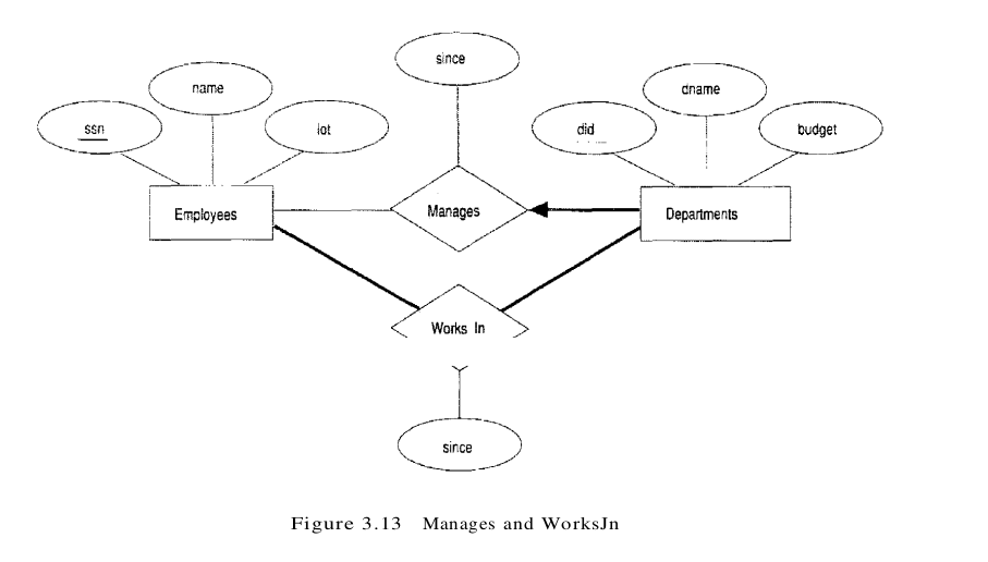
CREATE TABLE Dept_Mgr ( did INTEGER,
                    dname CHAR(20) ,
                    budget REAL,
                    ssn CHAR(11) NOT NULL,
                    since DATE,
                    PRIMARY KEY (did),
                    FOREIGN KEY (ssn) REFERENCES Employees ON DELETE NO ACTION)
It also captures the participation constraint that every department must have a manager: Because ssn cannot take on null values, each tuple of Dept_Mgr identifies a tuple in Employees (who is the manager). The NO ACTION specification, which is the default and need not be explicitly specified, ensures that an Employees tuple cannot be deleted while it is pointed to by a Dept_Mgr tuple. If we wish to delete such an Employees tuple, we must first change the Dept_Mgr tuple to have a new employee as manager. (We could have specified CASCADE instead of NO ACTION, but deleting all information about a department just because its manager has been fired seems a bit extreme!)
The constraint that every department must have a manager cannot be captured using the first translation approach discussed in the previous section. This situation is a strong argument in favor of using the second approach for one-to-many relationships such as Manages, especially when the entity set with the key constraint also has a total participation constraint.
Unfortunately, there are many participation constraints that we cannot capture using SQL, short of using table constraints or assertions. Table constraints and assertions can be specified using the full power of the SQL query language and are very expressive but also very expensive to check and enforce. For example, we cannot enforce the participation constraints on the Works_In relation without using these general constraints. To see why, consider the Works_In relation obtained by translating the ER diagram into relations. It contains fields ssn and did, which are foreign keys referring to Employees and Departments. To ensure total participation of Departments in Works_In, we have to guarantee that every did value in Departments appears in a tuple of Works_In. We could try to guarantee this condition by declaring that did in Departments is a foreign key referring to Works_In, but this is not a valid foreign key constraint because did is not a candidate key for Works_In.
To ensure total participation of Departments in Works_In using SQL, we need an assertion. We have to guarantee that every did value in Departments appears in a tuple of Works_In; further, this tuple of Works_In must also have non-null values in the fields that are foreign keys referencing other entity sets involved in the relationship (in this example, the ssn field). We can ensure the second part of this constraint by imposing the stronger requirement that ssn in Works_In cannot contain null values. (Ensuring that the participation of Employees in Works_In is total is symmetric.)
Another constraint that requires assertions to express in SQL is the requirement that each Employees entity (in the context of the Manages relationship set) must manage at least one department.
In fact, the Manages relationship set exemplifies most of the participation constraints that we can capture using key and foreign key constraints. Manages is a binary relationship set in which exactly one of the entity sets (Departments) has a key constraint, and the total participation constraint is expressed on that entity set.
We can also capture participation constraints using key and foreign key constraints in one other special situation: a relationship set in which all participating entity sets have key constraints and total participation. The best translation approach in this case is to map all the entities as well as the relationship into a single table; the details are straightforward.
Translating Weak Entity Sets
A weak entity set always participates in a one-to-many binary relationship and has a key constraint and total participation. The second translation approach discussed in previous section is ideal in this case, but we must take into account that the weak entity has only a partial key. Also, when an owner entity is deleted, we want all owned weak entities to be deleted.
Consider the Dependents weak entity set shown in Figure 3.14, with partial key pname. A Dependents entity can be identified uniquely only if we take the key of the owning Employees entity and the pname of the Dependents entity, and the Dependents entity must be deleted if the owning Employees entity is deleted.

We can capture the desired semantics with the following definition of the Dep_Policy relation:
CREATE TABLE Dep_Policy (pname CHAR(20) ,
                        age INTEGER,
                        cost REAL,
                        ssn CHAR (11) ,
                        PRIMARY KEY (pname, ssn),
                        FOREIGN KEY (ssn) REFERENCES Employees ON DELETE CASCADE )
Observe that the primary key is (pname, ssn) , since Dependents is a weak entity.
Translating Class Hierarchies
We present the two basic approaches to handling ISA hierarchies by applying them to the ER diagram shown in Figure 3.15:
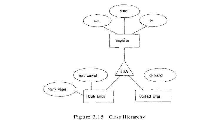
- We can map each of the entity sets Employees, Hourly_Emps, and Contract_Emps to a distinct relation. We discuss Hourly_Emps here; Contract_Emps is handled similarly. The relation for Hourly_Emps includes the hourly_wages and hours_worked attributes of Hourly_Emps. It also contains the key attributes of the superclass (ssn, in this example), which serve as the primary key for Hourly_Emps, as well as a foreign key referencing the superclass (Employees). For each Hourly_Emps entity, the value of the name and lot attributes are stored in the corresponding row of the superclass (Employees). Note that if the superclass tuple is deleted, the delete must be cascaded to Hourly_Emps.
- Alternatively, we can create just two relations, corresponding to Hourly_Emps and Contract_Emps. The relation for Hourly_Emps includes all the attributes of Hourly_Emps as well as all the attributes of Employees (i.e., ssn, name, lot, hourly_wages, hours_worked).
The first approach is general and always applicable.
Introduction to Views
A view is a table whose rows are not explicitly stored in the database but are computed as needed from a view definition. Consider the Students and Enrolled relations. Suppose we are often interested in finding the names and student identifiers of students who got a grade of B in some course, together with the course identifier. We can define a view for this purpose. Using SQL notation:
CREATE VIEW B-Students (name, sid, course)
                    AS SELECT S.sname, S.sid, E.cid
                    FROM Students S, Enrolled E
                    WHERE S.sid = E.studid AND E.grade = 'B'
The view B-Students has three fields called name, sid, and course with the same domains as the fields sname and sid in Students and cid in Enrolled. (If the optional arguments name, sid, and course are omitted from the CREATE VIEW statement, the column names sname, sid, and cid are inherited.)
The physical schema for a relational database describes how the relations in the conceptual schema are stored, in terms of the file organizations and indexes used. The conceptual schema is the collection of schemas of the relations stored in the database. While some relations in the conceptual schema can also be exposed to applications, that is, be part of the external schema of the database, additional relations in the external schema can be defined using the view mechanism. The view mechanism thus provides the support for logical data independence in the relational model. That is, it can be used to define relations in the external schema that mask changes in the conceptual schema of the database from applications. For example, if the schema of a stored relation is changed, we can define a view with the old schema and applications that expect to see the old schema can now use this view.
The motivation behind the view mechanism is to tailor how users see the data. Users should not have to worry about the view versus base table distinction. This goal is indeed achieved in the case of queries on views; a view can be used just like any other relation in defining a query. However, it is natural to want to specify updates on views as well. Here, unfortunately, the distinction between a view and a ba.se table must be kept in mind.