- end system
- access network
- ISPs (Internet Service Providers)
- requests for comments (RFCs)
- Distributed Application
- Digital Subscriber Line (DSL) and DSLAM
- Cable Modem Termination System (CMTS) and (HFC)
- Store and Forward Transmission
- FDM and TDM
- Total Nodal Delay
- Traffic Intensity
- Throughput In Computer Networks
- Internet Packets
- payload field
- DoS Attack (denial-of-service attack)
- IP Spoofing
In this post, I will introduce the common used glossary of computer network.
end system
In computer network, an end system, also called a host is the end point of the computer network.
access network
access network, the network that physically connects an end system to the first router on a path from the end system to any other distant end system.
ISPs (Internet Service Providers)
End systems access the Internet through Internet Service Providers (ISPs), including residential ISPs such as local cable or telephone companies; corporate ISPs; university ISPs; and ISPs that provide WiFi access in airports, hotels, coffee shops, and other public places. Each ISP is in itself a network of packet switches and communication links.
requests for comments (RFCs)
Internet standards are developed by the Internet Engineering Task Force (IETF). The IETF standards documents are called requests for comments (RFCs).
Distributed Application
These applications include electronic mail, Web surfing, social networks, instant messaging, Voice-over-IP (VoIP), video streaming, distributed games, peer-to-peer (P2P) file sharing, television over the Internet, remote login, and much, much more. The applications are said to be distributed applications, since they involve multiple end systems that exchange data with each other.
Digital Subscriber Line (DSL) and DSLAM
Digital Subscrbier Line Access Multiplexer (DSLAM)
A residence typically obtains DSL Internet access from the same local telephone company (telco) that provides its wired local phone access. Thus, when DSL is used, a customer’s telco is also its ISP. each customer’s DSL modem uses the existing telephone line (twisted-pair copper wire) to exchange data with a digital subscriber line access multiplexer (DSLAM) located in the telco’s local central office (CO). The home’s DSL modem takes digital data and translates it to high-frequency tones for transmission over telephone wires to the CO; the analog signals from many such houses are translated back into digital format at the DSLAM.
Cable Modem Termination System (CMTS) and (HFC)
Because both fiber and coaxial cable are employed in this system, it is often referred to as hybrid fiber coax (HFC).
Cable internet access requires special modems, called cable modems. As with a DSL modem, the cable modem is typically an external device and connects to the home PC through an Ethernet port. At the cable head end, the cable modem termination system (CMTS) serves a similar function as the DSL network’s DSLAM—turning the analog signal sent from the cable modems in many downstream homes back into digital format. Cable modems divide the HFC network into two channels, a downstream and an upstream channel. As with DSL, access is typically asymmetric, with the downstream channel typically allocated a higher transmission rate than the upstream channel.
Store and Forward Transmission
Store-and-forward transmission means that the packet switch must receive the entire packet before it can begin to transmit the first bit of the packet onto the outbound link.
FDM and TDM
frequency-division multiplexing (FDM)
time-division multiplexing (TDM)
One communication link may consist of multiple circuits. A circuit in a link is implemented with either FDM or TDM.
Total Nodal Delay
As a packet travels from one node (host or router) to the subsequent node (host or router) along this path, the packet suffers from several types of delays at each node along the path. The most important of these delays are the nodal processing delay, queuing delay, transmission delay, and propagation delay; together, these delays accumulate to give a total nodal delay.

The time required to examine the packet’s header and determine where to direct the packet is part of the processing delay. The processing delay can also include other factors, such as the time needed to check for bit-level errors in the packet that occurred in transmitting the packet’s bits from the upstream node to router A. Processing delays in high-speed routers are typically on the order of microseconds or less.
At the queue, the packet experiences a queuing delay as it waits to be transmitted onto the link. The length of the queuing delay of a specific packet will depend on the number of earlier-arriving packets that are queued and waiting for transmission onto the link. If the queue is empty and no other packet is currently being transmitted, then our packet’s queuing delay will be zero. On the other hand, if the traffic is heavy and many other packets are also waiting to be transmitted, the queuing delay will be long. We will see shortly that the number of packets that an arriving packet might expect to find is a function of the intensity and nature of the traffic arriving at the queue. Queuing delays can be on the order of microseconds to milliseconds in practice.
Assuming that packets are transmitted in a first-come-first-served manner, as is common in packet-switched networks, our packet can be transmitted only after all the packets that have arrived before it have been transmitted. Denote the length of the packet by L bits, and denote the transmission rate of the link from router A to router B by R bits/sec. For example, for a 10 Mbps Ethernet link, the rate is R = 10 Mbps; for a 100 Mbps Ethernet link, the rate is R = 100 Mbps. The transmission delay is L/R. This is the amount of time required to push all of the packet’s bits into the link. Transmission delays are typically on the order of microseconds to milliseconds in practice.
Once a bit is pushed into the link, it needs to propagate to router B. The time required to propagate from the beginning of the link to router B is the propagation delay. The bit propagates at the propagation speed of the link. The propagation speed depends on the physical medium of the link (that is, fiber optics, twisted-pair copper wire, and so on) and is in the range of $2 * 10^8$ meters/sec to $3 * 10^8$ meters/sec. In wide-area networks, propagation delays are on the order of milliseconds.
Traffic Intensity
Let a denote the average rate at which packets arrive at the queue (a is in units of packets/sec). Recall that R is the transmission rate; that is, it is the rate (in bits/sec) at which bits are pushed out of the queue. Also suppose, for simplicity, that all packets consist of L bits. Then the average rate at which bits arrive at the queue is La bits/sec. Finally, assume that the queue is very big, so that it can hold essentially an infinite number of bits. The ratio La/R, called the traffic intensity.
If La/R > 1, then the queue will tend to increase without bound and the queuing delay will approach infinity. Therefore, one of the golden rules in traffic engineering is: Design your system so that the traffic intensity is no greater than 1. However, because the queue capacity is finite, packet delays do not really approach infinity as the traffic intensity approaches 1.

Throughput In Computer Networks
The instantaneous throughput at any instant of time is the rate(in bits/sec) at which Host B is receiving the file. If the file consists of F bits and the transfer takes T seconds for Host B to receive all F bits, then the average throughput of the file transfer is F/T bits/sec.
Internet Packets
The application layer is where network applications and their application-layer protocols reside. We’ll refer to this packet of information at the application layer as a message.
The Internet’s transport layer transports application-layer messages between application endpoints. In the Internet there are two transport protocols, TCP and UDP, either of which can transport application-layer messages. In this book, we’ll refer to a transport-layer packet as a segment.
The Internet’s network layer is responsible for moving network-layer packets known as datagrams from one host to another.
The Internet’s network layer routes a datagram through a series of routers between the source and destination. To move a packet from one node (host or router) to the next node in the route, the network layer relies on the services of the link layer. In this book, we’ll refer to the link-layer packets as frames.
payload field
At each layer, a packet has two types of fields: header fields and a payload field. The payload is typically a packet from the layer above.
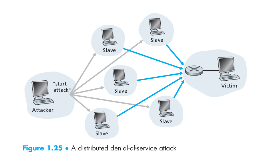
DoS Attack (denial-of-service attack)
Most Internet DoS attacks fall into one of three categories:
- Vulnerability attack. This involves sending a few well-crafted messages to a vulnerable application or operating system running on a targeted host. If the right sequence of packets is sent to a vulnerable application or operating system, the service can stop or, worse, the host can crash.
- Bandwidth flooding. The attacker sends a deluge of packets to the targeted host – so many packets that the target’s access link becomes clogged, preventing legitimate packets from reaching the server.
- Connection flooding. The attacker establishes a large number of half-open or fully open TCP connections at the target host. The host can become so bogged down with these bogus connections that it stops accepting legitimate connections.
DDoS attack, distributed Dos attack. In a distributed DoS (DDoS) attack, illustrated in the following image, the attacker controls multiple sources and has each source blast traffic at the target.
IP Spoofing
Imagine the unsuspecting receiver (say an Internet router) who receives such a packet, takes the (false) source address as being truthful, and then performs some command embedded in the packet’s contents (say modifies its forwarding table). The ability to inject packets into the Internet with a false source address is known as IP spoofing, and is but one of many ways in which one user can masquerade as another user.