- Wireless Links and Network Characteristics
- Code Division Multiple Access (CDMA)
- 802.11 Wireless LANs (WIFI)
We can identify the following elements in a wireless network:
- Wireless hosts. As in the case of wired networks, hosts are the end-system devices that run applications. A wireless host might be a laptop, palmtop, smartphone, or desktop computer. The hosts themselves may or may not be mobile.
- Wireless links. A host connects to a base station (defined below) or to another wireless host through a wireless communication link. Different wireless link technologies have different transmission rates and can transmit over different distances.
- Base station. The base station is a key part of the wireless network infrastructure. Unlike the wireless host and wireless link, a base station has no obvious counterpart in a wired network. A base station is responsible for sending and receiving data (e.g., packets) to and from a wireless host that is associated with that base station. A base station will often be responsible for coordinating the transmission of multiple wireless hosts with which it is associated. When we say a wireless host is “associated” with a base station, we mean that (1) the host is within the wireless communication distance of the base station, and (2) the host uses that base station to relay data between it (the host) and the larger network. Cell towers in cellular networks and access points in 802.11 wireless LANs are examples of base stations. Hosts associated with a base station are often referred to as operating in infrastructure mode, since all traditional network services (e.g., address assignment and routing) are provided by the network to which a host is connected via the base station. In ad hoc networks, wireless hosts have no such infrastructure with which to connect. In the absence of such infrastructure, the hosts themselves must provide for services such as routing, address assignment, DNS-like name translation, and more. When a mobile host moves beyond the range of one base station and into the range of another, it will change its point of attachment into the larger network (i.e., change the base station with which it is associated) – a process referred to as handoff.
At the highest level we can classify wireless networks according to two criteria: (i) whether a packet in the wireless network crosses exactly one wireless hop or multiple wireless hops, and (ii) whether there is infrastructure such as a base station in the network:
- Single-hop, infrastructure-based. These networks have a base station that is connected to a larger wired network (e.g., the Internet). Furthermore, all communication is between this base station and a wireless host over a single wireless hop. The 802.11 networks you use in the classroom, café, or library; and the 3G cellular data networks that we will learn about shortly all fall in this category.
- Single-hop, infrastructure-less. In these networks, there is no base station that is connected to a wireless network. However, as we will see, one of the nodes in this single-hop network may coordinate the transmissions of the other nodes. Bluetooth networks and 802.11 networks in ad hoc mode are single-hop, infrastructure-less networks.
- Multi-hop, infrastructure-based. In these networks, a base station is present that is wired to the larger network. However, some wireless nodes may have to relay their communication through other wireless nodes in order to communicate via the base station. Some wireless sensor networks and so-called wireless mesh networks fall in this category.
- Multi-hop, infrastructure-less. There is no base station in these networks, and nodes may have to relay messages among several other nodes in order to reach a destination. Nodes may also be mobile, with connectivity changing among nodes – a class of networks known as mobile ad hoc networks (MANETs). If the mobile nodes are vehicles, the network is a vehicular ad hoc network (VANET). As you might imagine, the development of protocols for such networks is challenging and is the subject of much ongoing research.
Wireless Links and Network Characteristics
Let’s begin by considering a simple wired network, say a home network, with a wired Ethernet switch interconnecting the hosts. If we replace the wired Ethernet with a wireless 802.11 network, a wireless network interface would replace the host’s wired Ethernet interface, and an access point would replace the Ethernet switch, but virtually no changes would be needed at the network layer or above. This suggests that we focus our attention on the link layer when looking for important differences between wired and wireless networks. Indeed, we can find a number of important differences between a wired link and a wireless link:
- Decreasing signal strength. Electromagnetic radiation attenuates as it passes through matter (e.g., a radio signal passing through a wall). Even in free space, the signal will disperse, resulting in decreased signal strength (sometimes referred to as path loss) as the distance between sender and receiver increases.
- Interference from other sources. Radio sources transmitting in the same frequency band will interfere with each other. For example, 2.4 GHz wireless phones and 802.11b wireless LANs transmit in the same frequency band. Thus, the 802.11b wireless LAN user talking on a 2.4 GHz wireless phone can expect that neither the network nor the phone will perform particularly well. In addition to interference from transmitting sources, electromagnetic noise within the environment (e.g., a nearby motor, a microwave) can result in interference.
- Multipath propagation. Multipath propagation occurs when portions of the electromagnetic wave reflect off objects and the ground, taking paths of different lengths between a sender and receiver. This results in the blurring of the received signal at the receiver. Moving objects between the sender and receiver can cause multipath propagation to change over time.
The discussion above suggests that bit errors will be more common in wireless links than in wired links. For this reason, it is perhaps not surprising that wireless link protocols employ not only powerful CRC error detection codes, but also link-level reliable-data-transfer protocols that retransmit corrupted frames. This host receives an electromagnetic signal that is a combination of a degraded form of the original signal transmitted by the sender (degraded due to the attenuation and multipath propagation effects that we discussed above, among others) and background noise in the environment. The signal-to-noise ratio (SNR) is a relative measure of the strength of the received signal (i.e., the information being transmitted) and this noise. For our purposes here, we need only know that a larger SNR makes it easier for the receiver to extract the transmitted signal from the background noise. The bit error rate (BER) – roughly speaking, the probability that a transmitted bit is received in error at the receiver. The following figure shows the modulation scheme with the SNR and BER.
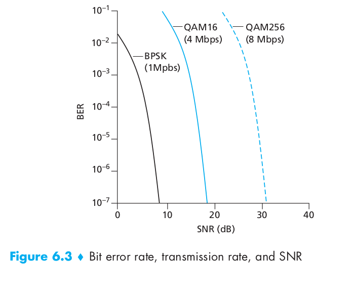
- For a given modulation scheme, the higher the SNR, the lower the BER. Since a sender can increase the SNR by increasing its transmission power, a sender can decrease the probability that a frame is received in error by increasing its transmission power. Note, however, that there is arguably little practical gain in increasing the power beyond a certain threshold, say to decrease the BER from 10 -12 to 10 -13 . There are also disadvantages associated with increasing the transmission power: More energy must be expended by the sender (an important concern for battery-powered mobile users), and the sender’s transmissions are more likely to interfere with the transmissions of another sender (see Figure 6.4(b)).
- For a given SNR, a modulation technique with a higher bit transmission rate (whether in error or not) will have a higher BER. For example, in Figure 6.3, with an SNR of 10 dB, BPSK modulation with a transmission rate of 1 Mbps has a BER of less than 10 -7 , while with QAM16 modulation with a transmission rate of 4 Mbps, the BER is 10 -1 , far too high to be practically useful. However, with an SNR of 20 dB, QAM16 modulation has a transmission rate of 4 Mbps and a BER of 10 -7 , while BPSK modulation has a transmission rate of only 1 Mbps and a BER that is so low as to be (literally) “off the charts.” If one can tolerate a BER of 10 -7 , the higher transmission rate offered by QAM16 would make it the preferred modulation technique in this situation. These considerations give rise to the final characteristic, described next.
- Dynamic selection of the physical-layer modulation technique can be used to adapt the modulation technique to channel conditions. The SNR (and hence the BER) may change as a result of mobility or due to changes in the environment. Adaptive modulation and coding are used in cellular data systems and in the 802.11 WiFi and 3G cellular data networks. This allows, for example, the selection of a modulation technique that provides the highest transmission rate possible subject to a constraint on the BER, for given channel characteristics.
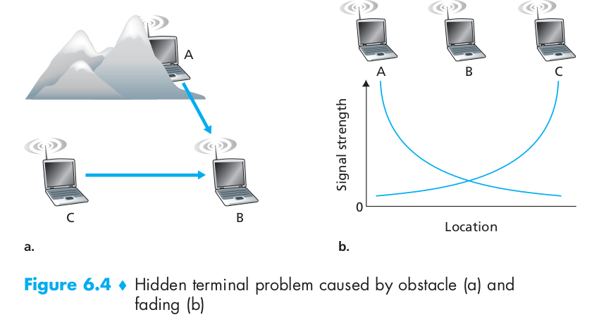
A higher and time-varying bit error rate is not the only difference between a wired and wireless link. Recall that in the case of wired broadcast links, all nodes receive the transmissions from all other nodes. In the case of wireless links, the situation is not as simple, as shown in Figure 6.4. Suppose that Station A is transmitting to Station B. Suppose also that Station C is transmitting to Station B. With the so-called hidden terminal problem, physical obstructions in the environment (for example, a mountain or a building) may prevent A and C from hearing each other’s transmissions, even though A’s and C’s transmissions are indeed interfering at the destination, B. This is shown in Figure 6.4(a). A second scenario that results in undetectable collisions at the receiver results from the fading of a signal’s strength as it propagates through the wireless medium. Figure 6.4(b) illustrates the case where A and C are placed such that their signals are not strong enough to detect each other’s transmissions, yet their signals are strong enough to interfere with each other at station B.
Code Division Multiple Access (CDMA)
In a CDMA protocol, each bit being sent is encoded by multiplying the bit by a signal (the code) that changes at a much faster rate (known as the chipping rate) than the original sequence of data bits. Figure 6.5 shows a simple, idealized CDMA encoding/decoding scenario. Suppose that the rate at which original data bits reach the CDMA encoder defines the unit of time; that is, each original data bit to be transmitted requires a one-bit slot time. Let $d_i$ be the value of the data bit for the ith bit slot. For mathematical convenience, we represent a data bit with a 0 value as –1. Each bit slot is further subdivided into M mini-slots; in Figure 6.5, M = 8, although in practice M is much larger. The CDMA code used by the sender consists of a sequence of M values, $c_m$ , m = 1, . . . , M, each taking a +1 or –1 value. In the example in Figure 6.5, the M-bit CDMA code being used by the sender is (1, 1, 1, –1, 1, –1, –1, –1). To illustrate how CDMA works, let us focus on the ith data bit, $d_i$. For the mth mini-slot of the bit-transmission time of $d_i$ , the output of the CDMA encoder, $Z_{i,m}$ , is the value of $d_i$ multiplied by the mth bit in the assigned CDMA code, $c_m$ (equation 6.1):
\[Z_{i, m}=d_{i} \cdot c_{m}\]In a simple world, with no interfering senders, the receiver would receive the encoded bits, $Z_{i,m}$ , and recover the original data bit, $d_i$ , by computing (equation 6.2):
\[d_{i}=\frac{1}{M} \sum_{m=1}^{M} Z_{i, m} \cdot c_{m}\]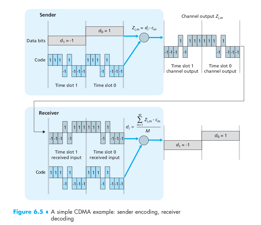
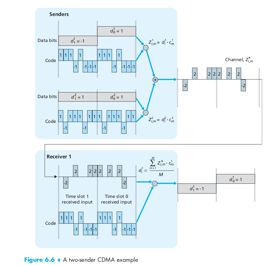
The world is far from ideal, however, and as noted above, CDMA must work in the presence of interfering senders that are encoding and transmitting their data using a different assigned code. But how can a CDMA receiver recover a sender’s original data bits when those data bits are being tangled with bits being transmitted by other senders? CDMA works under the assumption that the interfering transmitted bit signals are additive. This means, for example, that if three senders send a 1 value, and a fourth sender sends a –1 value during the same mini-slot, then the received signal at all receivers during that mini-slot is a 2 (since 1 + 1 + 1 - 1 = 2).In the presence of multiple senders, sender s computes its encoded transmissions, $Z_{i, m}$ exactly the same manner as in Equation 6.1. The value received at a receiver during the mth mini-slot of the ith bit slot, however, is now the sum of the transmitted bits from all N senders during that mini-slot. Amazingly, if the senders’ codes are chosen carefully, each receiver can recover the data sent by a given sender out of the aggregate signal simply by using the sender’s code in exactly the same manner as in Equation 6.2. as shown in Figure 6.6, for a two-sender CDMA example. The M-bit CDMA code being used by the upper sender is (1, 1, 1, –1, 1, –1, –1, –1), while the CDMA code being used by the lower sender is (1, –1, 1, 1, 1, –1, 1, 1). Figure 6.6 illustrates a receiver recovering the original data bits from the upper sender. Note that the receiver is able to extract the data from sender 1 in spite of the interfering transmission from sender 2.
802.11 Wireless LANs (WIFI)
The 802.11 Architecture
There are several 802.11 standards for wireless LAN technology, including 802.11b, 802.11a, and 802.11g. Table 6.1 summarizes the main characteristics of these standards. 802.11g is by far the most popular technology. A number of dual-mode (802.11a/g) and tri-mode (802.11a/b/g) devices are also available. The three 802.11 standards share many characteristics. They all use the same medium access protocol, CSMA/CA. All three standards have the ability to reduce their transmission rate in order to reach out over greater distances. And all three standards allow for both “infrastructure mode” and “ad hoc mode”. However, as shown in Table 6.1, the three standards have some major differences at the physical layer.

The fundamental building block of the 802.11 architecture is the basic service set (BSS). A BSS contains one or more wireless stations and a central base station, known as an access point (AP) in 802.11 parlance. As with Ethernet devices, each 802.11 wireless station has a 6-byte MAC address that is stored in the firmware of the station’s adapter (that is, 802.11 network interface card). Each AP also has a MAC address for its wireless interface. As with Ethernet, these MAC addresses are administered by IEEE and are (in theory) globally unique. Wireless LANs that deploy APs are often referred to as infrastructure wireless LANs, with the “infrastructure” being the APs along with the wired Ethernet infrastructure that interconnects the APs and a router. IEEE 802.11 stations can also group themselves together to form an ad hoc network – a network with no central control and with no connections to the “outside world.” Here, the network is formed “on the fly,” by mobile devices that have found themselves in proximity to each other, that have a need to communicate, and that find no preexisting network infrastructure in their location. An ad hoc network might be formed when people with laptops get together (for example, in a conference room, a train, or a car) and want to exchange data in the absence of a centralized AP. There has been tremendous interest in ad hoc networking, as communicating portable devices continue to proliferate.
In 802.11, each wireless station needs to associate with an AP before it can send or receive network-layer data. Although all of the 802.11 standards use association, we’ll discuss this topic specifically in the context of IEEE 802.11b/g. When a network administrator installs an AP, the administrator assigns a one-or two-word Service Set Identifier (SSID) to the access point. The administrator must also assign a channel number to the AP. To understand channel numbers, recall that 802.11 operates in the frequency range of 2.4 GHz to 2.485 GHz. Within this 85 MHz band, 802.11 defines 11 partially overlapping channels. Any two channels are non-overlapping if and only if they are separated by four or more channels. In particular, the set of channels 1, 6, and 11 is the only set of three non-overlapping channels. This means that an administrator could create a wireless LAN with an aggregate maximum transmission rate of 33 Mbps by installing three 802.11b APs at the same physical location, assigning channels 1, 6, and 11 to the APs, and interconnecting each of the APs with a switch.
A WiFi jungle is any physical location where a wireless station receives a sufficiently strong signal from two or more APs. Suppose there are five APs in the WiFi jungle. To gain Internet access, your wireless station needs to join exactly one of the subnets and hence needs to associate with exactly one of the APs. Associating means the wireless station creates a virtual wire between itself and the AP. Specifically, only the associated AP will send data frames (that is, frames containing data, such as a datagram) to your wireless station, and your wireless station will send data frames into the Internet only through the associated AP. The 802.11 standard requires that an AP periodically send beacon frames, each of which includes the AP’s SSID and MAC address. Your wireless station, knowing that APs are sending out beacon frames, scans the 11 channels, seeking beacon frames from any APs that may be out there (some of which may be transmitting on the same channel – it’s a jungle out there!). Having learned about available APs from the beacon frames, you (or your wireless host) select one of the APs for association.
The process of scanning channels and listening for beacon frames is known as passive scanning (see Figure 6.9a). A wireless host can also perform active scanning, by broadcasting a probe frame that will be received by all APs within the wireless host’s range, as shown in Figure 6.9b. APs respond to the probe request frame with a probe response frame. The wireless host can then choose the AP with which to associate from among the responding APs.

The 802.11 MAC Protocol
Once a wireless station is a ssociated with an AP, it can start sending and receiving data frames to and from the access point. But because multiple stations may want to transmit data frames at the same time over the same channel, a multiple access protocol is needed to coordinate the transmissions. Here, a station is either a wireless station or an AP. Inspired by the huge success of Ethernet and its random access protocol, the designers of 802.11 chose a random access protocol for 802.11 wireless LANs. This random access protocol is referred to as CSMA with collision avoidance, or more succinctly as CSMA/CA.
Although both Ethernet and 802.11 use carrier-sensing random access, the two MAC protocols have important differences. First, instead of using collision detection, 802.11 uses collision-avoidance techniques. Second, because of the relatively high bit error rates of wireless channels, 802.11 (unlike Ethernet) uses a link-layer acknowledgment/retransmission (ARQ) scheme. Unlike the 802.3 Ethernet protocol, the 802.11 MAC protocol does not implement collision detection. There are two important reasons for this:
- The ability to detect collisions requires the ability to send (the station’s own signal) and receive (to determine whether another station is also transmitting) at the same time. Because the strength of the received signal is typically very small compared to the strength of the transmitted signal at the 802.11 adapter, it is costly to build hardware that can detect a collision.
- More importantly, even if the adapter could transmit and listen at the same time (and presumably abort transmission when it senses a busy channel), the adapter would still not be able to detect all collisions, due to the hidden terminal problem and fading.
Because 802.11 wireless LANs do not use collision detection, once a station begins to transmit a frame, it transmits the frame in its entirety; that is, once a station gets started, there is no turning back. Before considering collision avoidance, however, we’ll first need to examine 802.11’s link-layer acknowledgment scheme. When a station in a wireless LAN sends a frame, the frame may not reach the destination station intact for a variety of reasons. To deal with this non-negligible chance of failure, the 802.11 MAC protocol uses link-layer acknowledgments. As shown in Figure 6.10, when the destination station receives a frame that passes the CRC, it waits a short period of time known as the Short Inter-frame Spacing (SIFS) and then sends back an acknowledgment frame. If the transmitting station does not receive an acknowledgment within a given amount of time, it assumes that an error has occurred and retransmits the frame, using the CSMA/CA protocol to access the channel. If an acknowledgment is not received after some fixed number of retransmissions, the transmitting station gives up and discards the frame. Having discussed how 802.11 uses link-layer acknowledgments, we’re now in a position to describe the 802.11 CSMA/CA protocol. Suppose that a station (wireless station or an AP) has a frame to transmit.
- If initially the station senses the channel idle, it transmits its frame after a short period of time known as the Distributed Inter-frame Space (DIFS); see Figure 6.10.
- Otherwise, the station chooses a random backoff value using binary exponential backoff and counts down this value when the channel is sensed idle. While the channel is sensed busy, the counter value remains frozen.
- When the counter reaches zero (note that this can only occur while the channel is sensed idle), the station transmits the entire frame and then waits for an acknowledgment.
- If an acknowledgment is received, the transmitting station knows that its frame has been correctly received at the destination station. If the station has another frame to send, it begins the CSMA/CA protocol at step 2. If the acknowledgment isn’t received, the transmitting station reenters the backoff phase in step 2, with the random value chosen from a larger interval.

Recall that under Ethernet’s CSMA/CD, multiple access protocol, a station begins transmitting as soon as the channel is sensed idle. With CSMA/CA, however, the station refrains from transmitting while counting down, even when it senses the channel to be idle. Why do CSMA/CD and CDMA/CA take such different approaches here? To answer this question, let’s consider a scenario in which two stations each have a data frame to transmit, but neither station transmits immediately because each senses that a third station is already transmitting. With Ethernet’s CSMA/CD, the two stations would each transmit as soon as they detect that the third station has finished transmitting. This would cause a collision, which isn’t a serious issue in CSMA/CD, since both stations would abort their transmissions and thus avoid the useless transmissions of the remainders of their frames. In 802.11, however, the situation is quite different. Because 802.11 does not detect a collision and abort transmission, a frame suffering a collision will be transmitted in its entirety. The goal in 802.11 is thus to avoid collisions whenever possible. In 802.11, if the two stations sense the channel busy, they both immediately enter random backoff, hopefully choosing different backoff values. If these values are indeed different, once the channel becomes idle, one of the two stations will begin transmitting before the other, and (if the two stations are not hidden from each other) the “losing station” will hear the “winning station’s” signal, freeze its counter, and refrain from transmitting until the winning station has completed its transmission. In this manner, a costly collision is avoided. Of course, collisions can still occur with 802.11 in this scenario: The two stations could be hidden from each other, or the two stations could choose random backoff values that are close enough that the transmission from the station starting first have yet to reach the second station.
Dealing with Hidden Terminals: RTS and CTS
The 802.11 MAC protocol also includes a nifty (but optional) reservation scheme that helps avoid collisions even in the presence of hidden terminals. Let’s now consider why hidden terminals can be problematic. Suppose Station H1 is transmitting a frame and halfway through H1’s transmission, Station H2 wants to send a frame to the AP. H2, not hearing the transmission from H1, will first wait a DIFS interval and then transmit the frame, resulting in a collision. The channel will therefore be wasted during the entire period of H1’s transmission as well as during H2’s transmission. In order to avoid this problem, the IEEE 802.11 protocol allows a station to use a short Request to Send (RTS) control frame and a short Clear to Send (CTS) control frame to reserve access to the channel. When a sender wants to send a DATA frame, it can first send an RTS frame to the AP, indicating the total time required to transmit the DATA frame and the acknowledgment (ACK) frame. When the AP receives the RTS frame, it responds by broadcasting a CTS frame. This CTS frame serves two purposes: It gives the sender explicit permission to send and also instructs the other stations not to send for the reserved duration. Thus, in Figure 6.12, before transmitting a DATA frame, H1 first broadcasts an RTS frame, which is heard by all stations in its circle, including the AP. The AP then responds with a CTS frame, which is heard by all stations within its range, including H1 and H2. Station H2, having heard the CTS, refrains from transmitting for the time specified in the CTS frame. The RTS, CTS, DATA, and ACK frames are shown in Figure 6.12.
The use of the RTS and CTS frames can improve performance in two important ways:
- The hidden station problem is mitigated, since a long DATA frame is transmitted only after the channel has been reserved.
- Because the RTS and CTS frames are short, a collision involving an RTS or CTS frame will last only for the duration of the short RTS or CTS frame. Once the RTS and CTS frames are correctly transmitted, the following DATA and ACK frames should be transmitted without collisions.
Although the RTS/CTS exchange can help reduce collisions, it also introduces delay and consumes channel resources. For this reason, the RTS/CTS exchange is only used (if at all) to reserve the channel for the transmission of a long DATA frame. In practice, each wireless station can set an RTS threshold such that the RTS/CTS sequence is used only when the frame is longer than the threshold. For many wireless stations, the default RTS threshold value is larger than the maximum frame length, so the RTS/CTS sequence is skipped for all DATA frames sent.

The WIFI Frame
Although the 802.11 frame shares many similarities with an Ethernet frame, it also contains a number of fields that are specific to its use for wireless links. The 802.11 frame is shown in Figure 6.13. The numbers above each of the fields in the frame represent the lengths of the fields in bytes; the numbers above each of the subfields in the frame control field represent the lengths of the subfields in bits.

- Payload and CRC Fields. At the heart of the frame is the payload, which typically consists of an IP datagram or an ARP packet. Although the field is permitted to be as long as 2,312 bytes, it is typically fewer than 1,500 bytes, holding an IP datagram or an ARP packet. As with an Ethernet frame, an 802.11 frame includes a 32-bit cyclic redundancy check (CRC) so that the receiver can detect bit errors in the received frame. As we’ve seen, bit errors are much more common in wireless LANs than in wired LANs, so the CRC is even more useful here.
- Address Fields Perhaps the most striking difference in the 802.11 frame is that it has four address fields, each of which can hold a 6-byte MAC address. But why four address fields? Doesn’t a source MAC field and destination MAC field suffice, as they do for Ethernet? It turns out that three address fields are needed for internetworking purposes – specifically, for moving the network-layer datagram from a wireless station through an AP to a router interface. The fourth address field is used when APs forward frames to each other in ad hoc mode. Since we are only considering infrastructure networks here, let’s focus our attention on the first three address fields. The 802.11 standard defines these fields as follows: Address 2 is the MAC address of the station that transmits the frame. Thus, if a wireless station transmits the frame, that station’s MAC address is inserted in the address 2 field. Similarly, if an AP transmits the frame, the AP’s MAC address is inserted in the address 2 field. Address 1 is the MAC address of the wireless station that is to receive the frame. Thus if a mobile wireless station transmits the frame, address 1 contains the MAC address of the destination AP. Similarly, if an AP transmits the frame, address 1 contains the MAC address of the destination wireless station. To understand address 3, recall that the BSS (consisting of the AP and wireless stations) is part of a subnet, and that this subnet connects to other subnets via some router interface. Address 3 contains the MAC address of this router interface.
To gain further insight into the purpose of address 3, let’s walk through an internetworking example in the context of Figure 6.14. In this figure, there are two APs, each of which is responsible for a number of wireless stations. Each of the APs has a direct connection to a router, which in turn connects to the global Internet. We should keep in mind that an AP is a link-layer device, and thus neither “speaks” IP nor understands IP addresses. Consider now moving a datagram from the router interface R1 to the wireless Station H1. The router is not aware that there is an AP between it and H1; from the router’s perspective, H1 is just a host in one of the subnets to which it (the router) is connected. The router, which knows the IP address of H1 (from the destination address of the datagram), uses ARP to determine the MAC address of H1, just as in an ordinary Ethernet LAN. After obtaining H1’s MAC address, router interface R1 encapsulates the datagram within an Ethernet frame. The source address field of this frame contains R1’s MAC address, and the destination address field contains H1’s MAC address. When the Ethernet frame arrives at the AP, the AP converts the 802.3 Ethernet frame to an 802.11 frame before transmitting the frame into the wireless channel. The AP fills in address 1 and address 2 with H1’s MAC address and its own MAC address, respectively, as described above. For address 3, the AP inserts the MAC address of R1. In this manner, H1 can determine (from address 3) the MAC address of the router interface that sent the datagram into the subnet. Now consider what happens when the wireless station H1 responds by moving a datagram from H1 to R1. H1 creates an 802.11 frame, filling the fields for address 1 and address 2 with the AP’s MAC address and H1’s MAC address, respectively, as described above. For address 3, H1 inserts R1’s MAC address. When the AP receives the 802.11 frame, it converts the frame to an Ethernet frame. The source address field for this frame is H1’s MAC address, and the destination address field is R1’s MAC address. Thus, address 3 allows the AP to determine the appropriate destination MAC address when constructing the Ethernet frame.

- Sequence Number, Duration, and Frame Control Fields Recall that in 802.11, whenever a station correctly receives a frame from another station, it sends back an acknowledgment. Because acknowledgments can get lost, the sending station may send multiple copies of a given frame. Recall that the 802.11 protocol allows a transmitting station to reserve the channel for a period of time that includes the time to transmit its data frame and the time to transmit an acknowledgment. This duration value is included in the frame’s duration field (both for data frames and for the RTS and CTS frames). As shown in Figure 6.13, the frame control field includes many subfields. We’ll say just a few words about some of the more important subfields; The type and subtype fields are used to distinguish the association, RTS, CTS, ACK, and data frames. The to and from fields are used to define the meanings of the different address fields.