- Transport-Layer Multiplexing and Demultiplexing
- Reliable Data Tansfer Mechanism
- GBN (Go Back N)
- SR (Selective Repeat)
- TCP (Transmission Control Protocol)
- sequence number and acknowledgment number
- Reliable Data Transfer Scenarios
- Flow Control
- Fast Retransmit
- Three-Way Handshake
- Closing TCP Connection
- SYN Flood Attack
- TCP Congestion Control
- UDP (User Datagram Protocol)
A transport-layer protocol provides logical communication between processes running on different hosts, a network-layer protocol provides logical communication between hosts.
Transport-Layer Multiplexing and Demultiplexing
Now let’s consider how a receiving host directs an incoming transport-layer segment to the appropriate socket. Each transport-layer segment has a set of fields in the segment for this purpose. At the receiving end, the transport layer examines these fields to identify the receiving socket and then directs the segment to that socket. This job of delivering the data in a transport-layer segment to the correct socket is called demultiplexing.
The job of gathering data chunks at the source host from different sockets, encapsulating each data chunk with header information to create segments, and passing the segments to the network layer is called multiplexing.
It is important to note that a UDP socket is fully identified by a two-tuple consisting of a destination IP address and a destination port number. As a consequence, if two UDP segments have different source IP addresses and/or source port numbers, but have the same destination IP address and destination port number, then the two segments will be directed to the same destination process via the same destination socket. One subtle difference between a TCP socket and a UDP socket is that a TCP socket is identified by a four-tuple: (source IP address, source port number, destination IP address, destination port number).
Reliable Data Tansfer Mechanism

GBN (Go Back N)
In a Go-Back-N (GBN) protocol, the sender is allowed to transmit multiple packets (when available) without waiting for an acknowledgment, but is constrained to have no more than some maximum allowable number, N, of unacknowledged packets in the pipeline. Flow control is one reason to impose a limit of the window size N of the GBN protocol on the sender.
If a timeout occurs, the sender resends all packets that have been previously sent but that have not yet been acknowledged.
In our GBN protocol, the receiver discards out-of-order packets. Although it may seem silly and wasteful to discard a correctly received (but out-of-order) packet, there is some justification for doing so. Recall that the receiver must deliver data in order to the upper layer. Suppose now that packet n is expected, but packet n + 1 arrives. Because data must be delivered in order, the receiver could buffer (save) packet n + 1 and then deliver this packet to the upper layer after it had later received and delivered packet n. However, if packet n is lost, both it and packet n + 1 will eventually be retransmitted as a result of the GBN retransmission rule at the sender. Thus, the receiver can simply discard packet n + 1.
SR (Selective Repeat)
The SR receiver will acknowledge a correctly received packet whether or not it is in order. Out-of-order packets are buffered until any missing packets (that is, packets with lower sequence numbers) are received, at which point a batch of packets can be delivered in order to the upper layer.

TCP (Transmission Control Protocol)
TCP offers several additional services to applications. First and foremost, it provides reliable data transfer. Using flow control, sequence numbers, acknowledgments, and timers. TCP ensures that data is delivered from sending process to receiving process, correctly and in order. TCP also provides congestion control.
A TCP connection provides a full-duplex service: If there is a TCP connection between Process A on one host and Process B on another host, then application-layer data can flow from Process A to Process B at the same time as application-layer data flows from Process B to Process A.
The maximum amount of data that can be grabbed and placed in a segment is limited by the maximum segment size (MSS). Note that the MSS is the maximum amount of application-layer data in the segment, not the maximum size of the TCP segment including headers. The MSS is typically set by first determining the length of the largest link-layer frame that can be sent by the local sending host (the so-called maximum transmission unit, MTU), and then setting the MSS to ensure that a TCP segment (when encapsulated in an IP datagram) plus the TCP/IP header length (typically 40 bytes) will fit into a single link-layer frame.
TCP pairs each chunk of client data with a TCP header, thereby forming TCP segments. The TCP segment consists of header fields and a data field. The data field contains a chunk of application data. As mentioned above, the MSS limits the maximum size of a segment’s data field. When TCP sends a large file, such as an image as part of a Web page, it typically breaks the file into chunks of size MSS (except for the last chunk, which will often be less than the MSS). The size of the TCP header is typically 20 bytes while the size of UDP header is 8 bytes.

sequence number and acknowledgment number
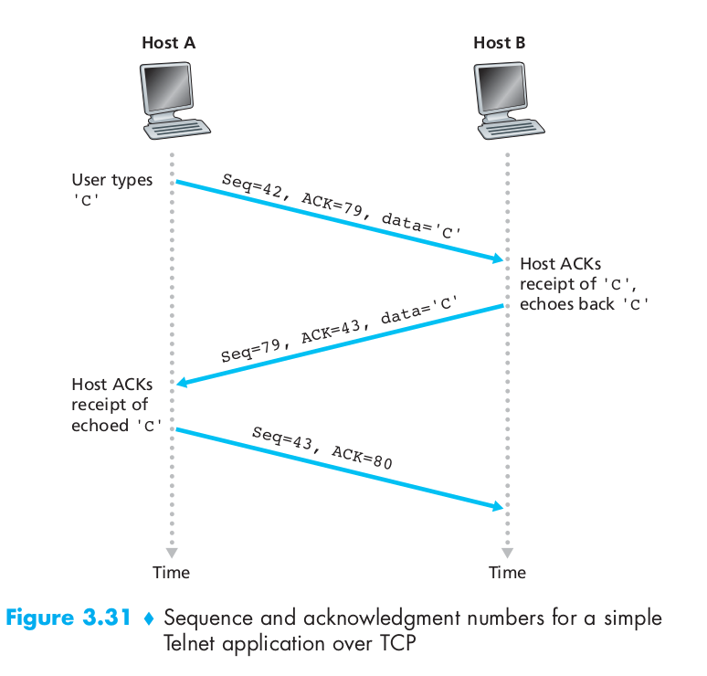
TCP views data as an unstructured, but ordered, stream of bytes. TCP’s use of sequence numbers reflects this view in that sequence numbers are over the stream of transmitted bytes and not over the series of transmitted segments. The sequence number for a segment is therefore the byte-stream number of the first byte in the segment. Let’s look at an example. Suppose that a process in Host A wants to send a stream of data to a process in Host B over a TCP connection. The TCP in Host A will implicitly number each byte in the data stream. Suppose that the data stream consists of a file consisting of 500,000 bytes, that the MSS is 1,000 bytes, and that the first byte of the data stream is numbered 0. Then TCP constructs 500 segments out of the data stream. The first segment gets assigned sequence number 0, the second segment gets assigned sequence number 1,000, the third segment gets assigned sequence number 2,000, and so on. Each sequence number is inserted in the sequence number field in the header of the appropriate TCP segment.
Recall that TCP is full-duplex, so that Host A may be receiving data from Host B while it sends data to Host B (as part of the same TCP connection). Each of the segments that arrive from Host B has a sequence number for the data flowing from B to A. The acknowledgment number that Host A puts in its segment is the sequence number of the next byte Host A is expecting from Host B. Suppose that Host A has received one segment from Host B containing bytes 0 through 535 and another segment containing bytes 900 through 1,000. For some reason Host A has not yet received bytes 536 through 899. In this example, Host A is still waiting for byte 536 (and beyond) in order to re-create B’s data stream. Thus, A’s next segment to B will contain 536 in the acknowledgment number field. Because TCP only acknowledges bytes up to the first missing byte in the stream, TCP is said to provide cumulative acknowledgment.
In truth, both sides of a TCP connection randomly choose an initial sequence number(ISN). This is done to minimize the possibility that a segment that is still present in the network from an earlier, already-terminated connection between two hosts is mistaken for a valid segment in a later connection between these same two hosts.
Reliable Data Transfer Scenarios
Suppose that this segment has sequence number 92 and contains 8 bytes of data. After sending this segment, Host A waits for a segment from B with acknowledgment number 100. Although the segment from A is received at B, the acknowledgment from B to A gets lost. In this case, the timeout event occurs, and Host A retransmits the same segment. Of course, when Host B receives the retransmission, it observes from the sequence number that the segment contains data that has already been received. Thus, TCP in Host B will discard the bytes in the retransmitted segment.
In a second scenario, Host A sends two segments back to back. The first segment has sequence number 92 and 8 bytes of data, and the second segment has sequence number 100 and 20 bytes of data. Suppose that both segments arrive intact at B, and B sends two separate acknowledgments for each of these segments. The first of these acknowledgments has acknowledgment number 100; the second has acknowledgment number 120. Suppose now that neither of the acknowledgments arrives at Host A before the timeout. When the timeout event occurs, Host A resends the first segment with sequence number 92 and restarts the timer. As long as the ACK for the second segment arrives before the new timeout, the second segment will not be retransmitted.
In a third and final scenario, suppose Host A sends the two segments, exactly as in the second example. The acknowledgment of the first segment is lost in the network, but just before the timeout event, Host A receives an acknowledgment with acknowledgment number 120. Host A therefore knows that Host B has received everything up through byte 119; so Host A does not resend either of the two segments.
So when the client didn’t successfully receive the expecting ACK segment, it will not always resend the oldest not acknowledged segment.
Flow Control
TCP provides a flow-control service to its applications to eliminate the possibility of the sender overflowing the receiver’s buffer. Flow control is thus a speed-matching service—matching the rate at which the sender is sending against the rate at which the receiving application is reading.
Even though the actions taken by flow and congestion control are similar (the throttling of the sender, they are obviously taken for very different reasons.
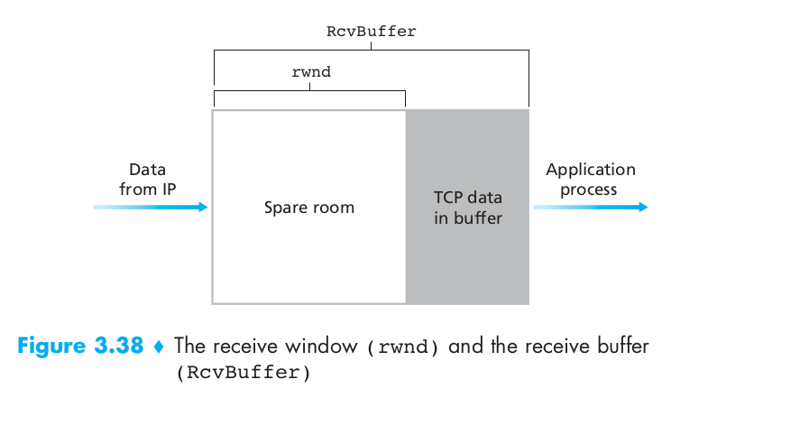
TCP provides flow control by having the sender maintain a variable called the receive window (rwnd). Suppose that Host A is sending a large file to Host B over a TCP connection. Host B allocates a receive buffer to this connection; denote its size by RcvBuffer. Host B tells Host A how much spare room it has in the connection buffer by placing its current value of rwnd in the receive window field of every segment it sends to A. Initially, Host B sets rwnd = RcvBuffer. Host A in turn keeps track of two variables, LastByteSent and LastByteAcked, which have obvious meanings. Note that the difference between these two variables, LastByteSent – LastByteAcked, is the amount of unacknowledged data that A has sent into the connection. By keeping the amount of unacknowledged data less than the value of rwnd, Host A is assured that it is not overflowing the receive buffer at Host B. Thus, Host A makes sure throughout the connection’s life that \(LastByteSent – LastByteAcked <= rwnd\)
Fast Retransmit
One of the problems with timeout-triggered retransmissions is that the timeout period can be relatively long. When a segment is lost, this long timeout period forces the sender to delay resending the lost packet, thereby increasing the end-to-end delay. Fortunately, the sender can often detect packet loss well before the timeout event occurs by noting so-called duplicate ACKs. A duplicate ACK is an ACK that reacknowledges a segment for which the sender has already received an earlier acknowledgment.
Since TCP does not use negative acknowledgments, the receiver cannot send an explicit negative acknowledgment back to the sender. Instead, it simply reacknowledges (that is, generates a duplicate ACK for) the last in-order byte of data it has received. Because a sender often sends a large number of segments back to back, if one segment is lost, there will likely be many back-to-back duplicate ACKs. If the TCP sender receives three duplicate ACKs for the same data, it takes this as an indication that the segment following the segment that has been ACKed three times has been lost. In the case that three duplicate ACKs are received, the TCP sender performs a fast retransmit [RFC 5681], retransmitting the missing segment before that segment’s timer expires. This is shown in Figure 3.37, where the second segment is lost, then retransmitted before its timer expires.

Three-Way Handshake
The client application process first informs the client TCP that it wants to establish a connection to a process in the server. The TCP in the client then proceeds to establish a TCP connection with the TCP in the server in the following manner:
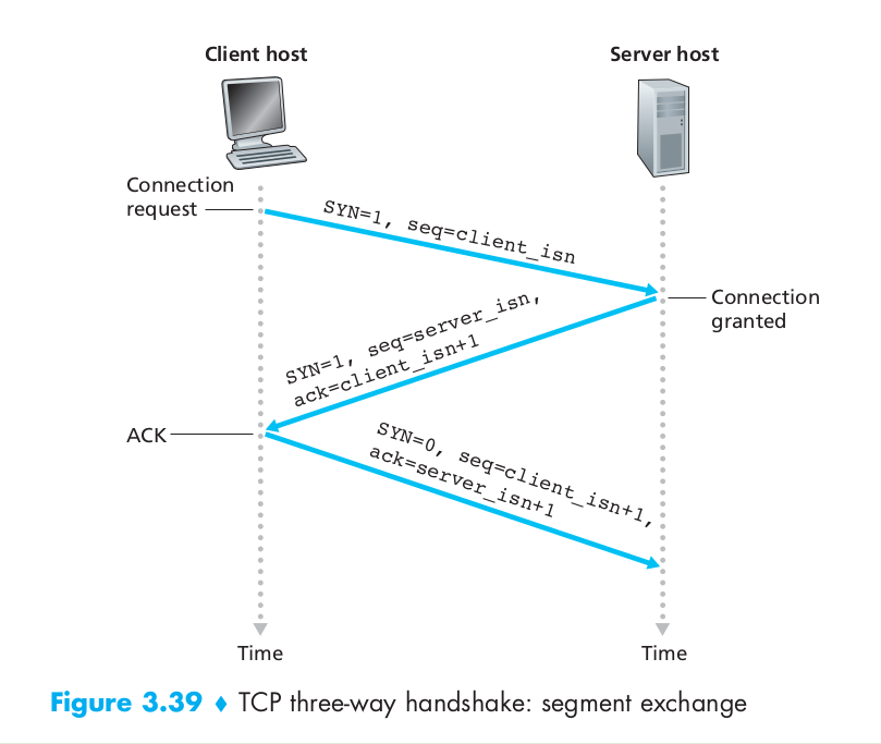
- The client-side TCP first sends a special TCP segment to the server-side TCP. This special segment contains no application-layer data. But one of the flag bits in the segment’s header, the SYN bit, is set to 1. For this reason, this special segment is referred to as a SYN segment. In addition, the client randomly chooses an initial sequence number (client_isn) and puts this number in the sequence number field of the initial TCP SYN segment. This segment is encapsulated within an IP datagram and sent to the server. There has been considerable interest in properly randomizing the choice of the client_isn in order to avoid certain security attacks.
- Once the IP datagram containing the TCP SYN segment arrives at the server host (assuming it does arrive!), the server extracts the TCP SYN segment from the datagram, allocates the TCP buffers and variables to the connection, and sends a connection-granted segment to the client TCP. (The allocation of these buffers and variables before completing the third step of the three-way handshake makes TCP vulnerable to a denial-of-service attack known as SYN flooding.) This connection-granted segment also contains no application-layer data. However, it does contain three important pieces of information in the segment header. First, the SYN bit is set to 1. Second, the acknowledgment field of the TCP segment header is set to client_isn + 1. Finally, the server chooses its own initial sequence number (server_isn) and puts this value in the sequence number field of the TCP segment header. This connection-granted segment is saying, in effect, “I received your SYN packet to start a connection with your initial sequence number, client_isn. I agree to establish this connection. My own initial sequence number is server_isn.” The connection-granted segment is referred to as a SYNACK segment.
- Upon receiving the SYNACK segment, the client also allocates buffers and variables to the connection. The client host then sends the server yet another segment; this last segment acknowledges the server’s connection-granted segment (the client does so by putting the value server_isn+1 in the acknowledgment field of the TCP segment header). The SYN bit is set to zero, since the connection is established. This third stage of the three-way handshake may carry client-to-server data in the segment payload.
Once these three steps above have been completed, the client and server hosts can send segments containing data to each other. In each of these future segments, the SYN bit will be set to zero.
Closing TCP Connection
Either of the two processes participating in a TCP connection can end the connection. When a connection ends, the “resources” (that is, the buffers and variables) in the hosts are deallocated. As an example, suppose the client decides to close the connection, as shown in Figure 3.40.


The client TCP begins in the CLOSED state. The application on the client side initiates a new TCP connection. This causes TCP in the client to send a SYN segment to TCP in the server. After having sent the SYN segment, the client TCP enters the SYN_SENT state. While in the SYN_SENT state, the client TCP waits for a segment from the server TCP that includes an acknowledgment for the client’s previous segment and has the SYN bit set to 1. Having received such a segment, the client TCP enters the ESTABLISHED state. While in the ESTABLISHED state, the TCP client can send and receive TCP segments containing payload (that is, application-generated) data. Suppose that the client application decides it wants to close the connection. (Note that the server could also choose to close the connection.) This causes the client TCP to send a TCP segment with the FIN bit set to 1 and to enter the FIN_WAIT_1 state. While in the FIN_WAIT_1 state, the client TCP waits for a TCP segment from the server with an acknowledgment. When it receives this segment, the client TCP enters the FIN_WAIT_2 state. While in the FIN_WAIT_2 state, the client waits for another segment from the server with the FIN bit set to 1; after receiving this segment, the client TCP acknowledges the server’s segment and enters the TIME_WAIT state. The TIME_WAIT state lets the TCP client resend the final acknowledgment in case the ACK is lost. The time spent in the TIME_WAIT state is implementation-dependent, but typical values are 30 seconds, 1 minute, and 2 minutes. The duration that this endpoint remains in this state is twice the maximum segment lifetime (MSL), sometimes called 2MSL.
There are reasons for the TIME_WAIT state.
- Try the best to make sure the other host can receive the last ACK segment.
- Leaving enough time for the hosts to drop the outdated segments of the closing connection so that the next connection will not receive the segments of the previous connection.
The first reason can be explained by looking at Figure 2.5 and assuming that the final ACK is lost. The server will resend its final FIN, so the client must maintain state information, allowing it to resend the final ACK. If it did not maintain this information, it would respond with an RST (a different type of TCP segment), which would be interpreted by the server as an error. This example also shows why the end that performs the active close is the end that remains in the TIME_WAIT state: because that end is the one that might have to retransmit the final ACK.

To understand the second reason for the TIME_WAIT state, assume we have a TCP connection between 12.106.32.254 port 1500 and 206.168.112.219 port 21. This connection is closed and then sometime later, we establish another connection between the same IP addresses and ports: 12.106.32.254 port 1500 and 206.168.112.219 port 21. This latter connection is called an incarnation of the previous connection since the IP addresses and ports are the same. TCP must prevent old duplicates from a connection from reappearing at some later time and being misinterpreted as belonging to a new incarnation of the same connection. To do this, TCP will not initiate a new incarnation of a connection that is currently in the TIME_WAIT state. Since the duration of the TIME_WAIT state is twice the MSL, this allows MSL seconds for a packet in one direction to be lost, and another MSL seconds for the reply to be lost. By enforcing this rule, we are guaranteed that when we successfully establish a TCP connection, all old duplicates from previous incarnations of the connection have expired in the network.
After the wait, the connection formally closes and all resources on the client side (including port numbers) are released.

SYN Flood Attack
In this attack, the attacker(s) send a large number of TCP SYN segments, without completing the third handshake step. With this deluge of SYN segments, the server’s connection resources become exhausted as they are allocated (but never used!) for half-open connections; legitimate clients are then denied service. Such SYN flooding attacks were among the first documented DoS attacks [CERT SYN 1996]. Fortunately, an effective defense known as SYN cookies [RFC 4987] are now deployed in most major operating systems. SYN cookies work as follows:
- When the server receives a SYN segment, it does not know if the segment is coming from a legitimate user or is part of a SYN flood attack. So, instead of creating a half-open TCP connection for this SYN, the server creates an initial TCP sequence number that is a complicated function (hash function) of source and destination IP addresses and port numbers of the SYN segment, as well as a secret number only known to the server. This carefully crafted initial sequence number is the so-called “cookie.” The server then sends the client a SYNACK packet with this special initial sequence number. Importantly, the server does not remember the cookie or any other state information corresponding to the SYN.
- A legitimate client will return an ACK segment. When the server receives this ACK, it must verify that the ACK corresponds to some SYN sent earlier. But how is this done if the server maintains no memory about SYN segments? As you may have guessed, it is done with the cookie. Recall that for a legitimate ACK, the value in the acknowledgment field is equal to the initial sequence number in the SYNACK (the cookie value in this case) plus one. The server can then run the same hash function using the source and destination IP address and port numbers in the SYNACK (which are the same as in the original SYN) and the secret number. If the result of the function plus one is the same as the acknowledgment (cookie) value in the client’s SYNACK, the server concludes that the ACK corresponds to an earlier SYN segment and is hence valid. The server then creates a fully open connection along with a socket.
- On the other hand, if the client does not return an ACK segment, then the original SYN has done no harm at the server, since the server hasn’t yet allocated any resources in response to the original bogus SYN.
TCP Congestion Control
End-to-end congestion control. In an end-to-end approach to congestion control, the network layer provides no explicit support to the transport layer for congestion-control purposes. Even the presence of congestion in the network must be inferred by the end systems based only on observed network behavior (for example, packet loss and delay). TCP must necessarily take this end-to-end approach toward congestion control, since the IP layer provides no feedback to the end systems regarding network congestion. TCP segment loss (as indicated by a timeout or a triple duplicate acknowledgment) is taken as an indication of network congestion and TCP decreases its window size accordingly. We will also see a more recent proposal for TCP congestion control that uses increasing round-trip delay values as indicators of increased network congestion.
Let’s first examine how a TCP sender limits the rate at which it sends traffic into its connection. The TCP congestion-control mechanism operating at the sender keeps track of an additional variable, the congestion window. The congestion window, denoted cwnd, imposes a constraint on the rate at which a TCP sender can send traffic into the network. Specifically, the amount of unacknowledged data at a sender may not exceed the minimum of cwnd and rwnd, that is:
\[LastByteSent – LastByteAcked <= min\{cwnd, rwnd\}\]Consider a connection for which loss and packet transmission delays are negligible. Then, roughly, at the beginning of every RTT, the constraint permits the sender to send cwnd bytes of data into the connection; at the end of the RTT the sender receives acknowledgments for the data. Thus the sender’s send rate is roughly cwnd/RTT bytes/sec. By adjusting the value of cwnd, the sender can therefore adjust the rate at which it sends data into its connection.
A lost segment implies congestion, and hence, the TCP sender’s rate should be decreased when a segment is lost. An acknowledged segment indicates that the network is delivering the sender’s segments to the receiver, and hence, the sender’s rate can be increased when an ACK arrives for a previously unacknowledged segment. The TCP congestion-control algorithm has three major components: 1. slow start. 2. congestion avoidance. 3. fast recovery.
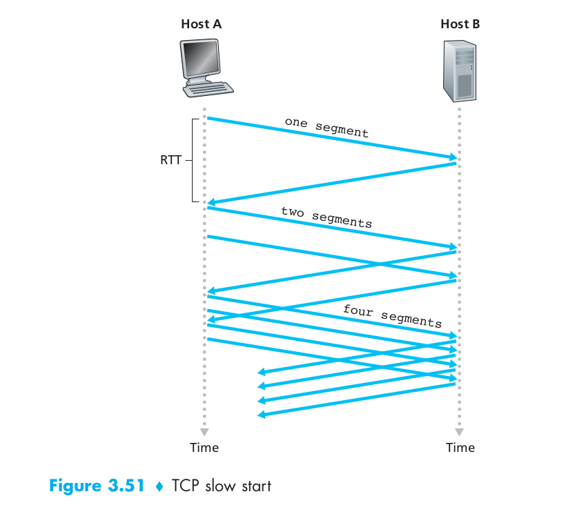
For slow start, When a TCP connection begins, the value of cwnd is typically initialized to a small value of 1 MSS [RFC 3390], resulting in an initial sending rate of roughly MSS/RTT. Since the available bandwidth to the TCP sender may be much larger than MSS/RTT, the TCP sender would like to find the amount of available bandwidth quickly. Thus, in the slow-start state, the value of cwnd begins at 1 MSS and increases by 1 MSS every time a transmitted segment is first acknowledged. TCP sends the first segment into the network and waits for an acknowledgment. When this acknowledgment arrives, the TCP sender increases the congestion window by one MSS and sends out two maximum-sized segments. These segments are then acknowledged, with the sender increasing the congestion window by 1 MSS for each of the acknowledged segments, giving a congestion window of 4 MSS, and so on. This process results in a doubling of the sending rate every RTT. Thus, the TCP send rate starts slow but grows exponentially during the slow start phase. If there is a loss event (i.e., congestion) indicated by a timeout, the TCP sender sets the value of cwnd to 1 and begins the slow start process anew. It also sets the value of a second state variable, ssthresh (shorthand for “slow start threshold”) to cwnd/2—half of the value of the congestion window value when congestion was detected.
The second way in which slow start may end is directly tied to the value of ssthresh. Since ssthresh is half the value of cwnd when congestion was last detected, it might be a bit reckless to keep doubling cwnd when it reaches or surpasses the value of ssthresh. Thus, when the value of cwnd equals ssthresh, slow start ends and TCP transitions into congestion avoidance mode.
For congestion avoidance, rather than doubling the value of cwnd every RTT, TCP adopts a more conservative approach and increases the value of cwnd by just a single MSS every RTT [RFC 5681]. This can be accomplished in several ways. A common approach is for the TCP sender to increase cwnd by MSS bytes (MSS/cwnd) whenever a new acknowledgment arrives. For example, if MSS is 1,460 bytes and cwnd is 14,600 bytes, then 10 segments are being sent within an RTT. Each arriving ACK (assuming one ACK per segment) increases the congestion window size by 1/10 MSS, and thus, the value of the congestion window will have increased by one MSS after ACKs when all 10 segments have been received.
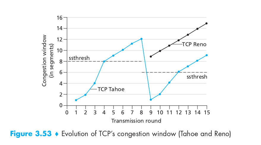
For Fast Recovery, it is a recommended, but not required, component of TCP [RFC 5681]. It is interesting that an early version of TCP, known as TCP Tahoe, unconditionally cut its congestion window to 1 MSS and entered the slow-start phase after either a timeout-indicated or triple-duplicate-ACK-indicated loss event. The newer version of TCP, TCP Reno, incorporated fast recovery. The image below shows the curve of the congestion window during fast recovery.
UDP (User Datagram Protocol)
UDP, defined in [RFC 768], does just about as little as a transport protocol can do. Aside from the multiplexing/demultiplexing function and some light error checking, it adds nothing to IP. In fact, if the application developer chooses UDP instead of TCP, then the application is almost directly talking with IP. UDP takes messages from the application process, attaches source and destination port number fields for the multiplexing/demultiplexing service, adds two other small fields, and passes the resulting segment to the network layer. The network layer encapsulates the transport-layer segment into an IP datagram and then makes a best-effort attempt to deliver the segment to the receiving host. If the segment arrives at the receiving host, UDP uses the destination port number to deliver the segment’s data to the correct application process. Note that with UDP there is no handshaking between sending and receiving transport-layer entities before sending a segment. For this reason, UDP is said to be connectionless.
Now you might be wondering why an application developer would ever choose to build an application over UDP rather than over TCP. Isn’t TCP always preferable, since TCP provides a reliable data transfer service, while UDP does not? The answer is no, as many applications are better suited for UDP for the following reasons:
- Finer application-level control over what data is sent, and when. Under UDP, as soon as an application process passes data to UDP, UDP will package the data inside a UDP segment and immediately pass the segment to the network layer. TCP, on the other hand, has a congestion-control mechanism that throttles the transport-layer TCP sender when one or more links between the source and destination hosts become excessively congested. TCP will also continue to resend a segment until the receipt of the segment has been acknowledged by the destination, regardless of how long reliable delivery takes. Since real-time applications often require a minimum sending rate, do not want to overly delay segment transmission, and can tolerate some data loss, TCP’s service model is not particularly well matched to these applications’ needs. As discussed below, these applications can use UDP and implement, as part of the application, any additional functionality that is needed beyond UDP’s no-frills segment-delivery service.
- No connection establishment. TCP uses a three-way handshake before it starts to transfer data. UDP just blasts away without any formal preliminaries. Thus UDP does not introduce any delay to establish a connection. This is probably the principal reason why DNS runs over UDP rather than TCP – DNS would be much slower if it ran over TCP. HTTP uses TCP rather than UDP, since reliability is critical for Web pages with text. But, the TCP connection-establishment delay in HTTP is an important contributor to the delays associated with downloading Web documents.
- No connection state. TCP maintains connection state in the end systems. This connection state includes receive and send buffers, congestion-control parameters, and sequence and acknowledgment number parameters. This state information is needed to implement TCP’s reliable data transfer service and to provide congestion control. UDP, on the other hand, does not maintain connection state and does not track any of these parameters. For this reason, a server devoted to a particular application can typically support many more active clients when the application runs over UDP rather than TCP.
- Small packet header overhead. The TCP segment has 20 bytes of header overhead in every segment, whereas UDP has only 8 bytes of overhead.
The UDP segment struture as the following image shows:
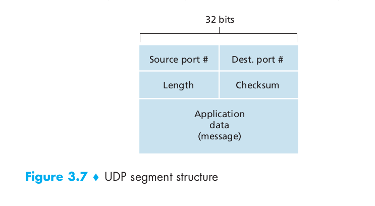
The UDP checksum provides for error detection. That is, the checksum is used to determine whether bits within the UDP segment have been altered (for example, by noise in the links or while stored in a router) as it moved from source to destination.