- Database Design and ER Diagrams
- Entities, Attributes and Entity Sets
- Relationships and Relationship Sets
- Additonal Features of the ER Model
- Conceptual Design with the ER Model
Database Design and ER Diagrams
The database design process can be divided into six steps. The ER model is most relevant to the first three steps. Within the larger context of the overall design process, the ER model is used in a phase called conceptual database design.
- Requirements Analysis: The very first step in designing a database application is to understand what data is to be stored in the database, what applications must be built on top of it, and what operations are most frequent and subject to performance requirements. In other words, we must find out what the users want from the database. This is usually an informal process that involves discussions with user groups, a study of the current operating environment and how it is expected to change, analysis of any available documentation on existing applications that are expected to be replaced or complemented by the database, and so on. Several methodologies have been proposed for organizing and presenting the information gathered in this step, and some automated tools have been developed to support this process.
- Conceptual Database Design: The information gathered in the requirements analysis step is used to develop a high-level description of the data to be stored in the database, along with the constraints known to hold over this data. This step is often carried out using the ER model. The ER model is one of several high-level, or semantic, data models used in database design. The goal is to create a simple description of the data that closely matches how users and developers think of the data (and the people and processes to be represented in the data). This facilitates discussion among all the people involved in the design process, even those who have no technical background. At the same time, the initial design must be sufficiently precise to enable a straightforward translation into a data model supported by a commercial database system (which, in practice, means the relational model).
- Logical Database Design: We must choose a DBMS to implement our database design, and convert the conceptual database design into a database schema in the data model of the chosen DBMS. We will consider only relational DBMSs, and therefore, the task in the logical design step is to convert an ER schema into a relational database schema. The result is a conceptual schema, sometimes called the logical schema, in the relational data model.
- Schema Refinement: The fourth step of database design is to analyze the collection of relations in our relational database schema to identify potential problems, and to refine it. In contrast to the requirements analysis and conceptual design steps, which are essentially subjective, schema refinement can be guided by some elegant and powerful theory.
- Physical Database Design: In this step, we consider typical expected workloads that our database must support and further refine the database design to ensure that it meets desired performance criteria. This step may simply involve building indexes on some tables and clustering some tables, or it may involve a substantial redesign of parts of the database schema obtained from the earlier design steps.
- Application and Security Design: Any software project that involves a DBMS must consider aspects of the application that go beyond the database itself. Design methodologies like UML try to address the complete software design and development cycle. Briefly, we must identify the entities (e.g., users, user groups, departments) and processes involved in the application. We must describe the role of each entity in every process that is reflected in some application task, as part of a complete workflow for that task. For each role, we must identify the parts of the database that must be accessible and the parts of the database that must not be accessible, and we must take steps to ensure that these access rules are enforced. A DBMS provides several mechanisms to assist in this step.
Entities, Attributes and Entity Sets
An entity is an object in the real world that is distinguishable from other objects. Examples include the following: the Green Dragonzord toy, the toy department, the manager of the toy department, the home address of the manager of the toy department. It is often useful to identify a collection of similar entities. Such a collection is called an entity set. Note that entity sets need not be disjoint; the collection of toy department employees and the collection of appliance department employees may both contain employee John Doe (who happens to work in both departments). We could also define an entity set called Employees that contains both the toy and appliance department employee sets.
An entity is described using a set of attributes. All entities in a given entity set have the same attributes; this is what we mean by similar. (This statement is an oversimplification, as we will see when we discuss inheritance hierarchies, but it suffices for now and highlights the main idea.) Our choice of attributes reflects the level of detail at which we wish to represent information about entities. For example, the Employees entity set could use name, social security number (ssn), and parking lot (lot) as attributes. In this case we will store the name, social security number, and lot number for each employee. However, we will not store, say, an employee’s address (or gender or age).
For each attribute associated with an entity set, we must identify a domain of possible values. For example, the domain associated with the attribute name of Employees might be the set of 20-character strings. Further, for each entity set, we choose a key. A key is a minimal set of attributes whose values uniquely identify an entity in the set. There could be more than one candidate key; if so, we designate one of them as the primary key. For now we assume that each entity set contains at least one set of attributes that uniquely identifies an entity in the entity set; that is, the set of attributes contains a key.
Relationships and Relationship Sets
A relationship is an association among two or more entities. For example, we may have the relationship that Attishoo works in the pharmacy department. As with entities, we may wish to collect a set of similar relationships into a relationship set. A relationship set can be thought of as a set of n-tuples:
\[\{\left(e_{1}, \ldots, e_{n}\right) \mid e_{1} \in E_{1}, \ldots, e_{n} \in E_{n}\}\]Each n-tuple denotes a relationship involving n entities $e_1$ through $e_n$, where entity $e_i$ is in entity set $E_i$ . In Figure 2.2 we show the relationship set Works_In, in which each relationship indicates a department in which an employee works. Note that several relationship sets might involve the same entity sets. For example, we could also have a Manages relationship set involving Employees and Departments.
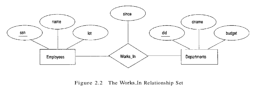
A relationship can also have descriptive attributes. Descriptive attributes are used to record information about the relationship, rather than about any one of the participating entities; for example, we may wish to record that Attishoo works in the pharmacy department as of January 1991. This information is captured in Figure 2.2 by adding an attribute, since, to Works_In. A relationship must be uniquely identified by the participating entities, without reference to the descriptive attributes. In the Works_In relationship set, for example, each Works_In relationship must be uniquely identified by the combination of employee ssn and department did. Thus, for a given employee-department pair, we cannot have more than one associated since value.
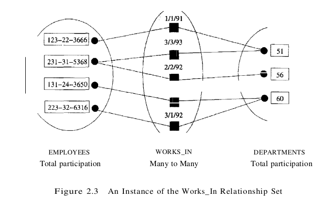
An instance of a relationship set is a set of relationships. Intuitively, an instance can be thought of as a ‘snapshot’ of the relationship set at some instant in time. An instance of the works_in relationship set is shown in Figure 2.3. Each Employees entity is denoted by its ssn, and each Departments entity is denoted by its did, for simplicity. The since value is shown beside each relationship.
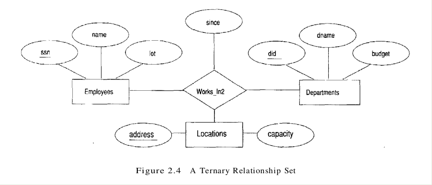
As another example of an ER diagram, suppose that each department has offices in several locations and we want to record the locations at which each employee works. This relationship is ternary because we must record an association between an employee, a department, and a location. The ER diagram for this variant of Works_In, which we call Works_In2, is shown in Figure 2.4.
The entity sets that participate in a relationship set need not be distinct; sometimes a relationship might involve two entities in the same entity set. For example, consider the Reports_To relationship set shown in Figure 2.5. Since employees report to other employees, every relationship in Reports_To is of the form (emp1. emp2), where both emp1 and emp2 are entities in Employees. However, they play different roles: emp1 reports to the managing employee emp2, which is reflected in the role indicators supervisor and subordinate in Figure 2.5. If an entity set plays more than one role, the role indicator concatenated with an attribute name from the entity set gives us a unique name for each attribute in the relationship set. For example, the Reports_To relationship set has attributes corresponding to the ssn of the supervisor and the ssn of the subordinate, and the names of these attributes are supervisor_ssn and subordinate-ssn.

Additonal Features of the ER Model
Key Constraints
Consider the Works_In relationship shown in Figure 2.2. An employee can work in several departments, and a department can have several employees, as illustrated in the Works_In instance shown in Figure 2.3. Employee 231-31-5368 has worked in Department 51 since 3/3/93 and in Department 56 since 2/2/92. Department 51 has two employees.
Now consider another relationship set called Manages between the Employees and Departments entity sets such that each department has at most one manager, although a single employee is allowed to manage more than one department. The restriction that each department has at most one manager is an example of a key constraint, and it implies that each Departments entity appears in at most one Manages relationship in any allowable instance of Manages. This restriction is indicated in the ER diagram of Figure 2.6 by using an arrow from Departments to Manages. Intuitively, the arrow states that given a Departments entity, we can uniquely determine the Manages relationship in which it appears.
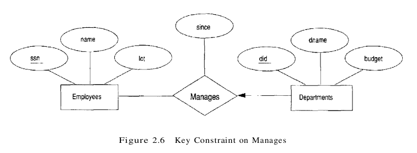
An instance of the Manages relationship set is shown in Figure 2.7. While this is also a potential instance for the Works_In relationship set, the instance of Works_In shown in Figure 2.3 violates the key constraint on Manages.
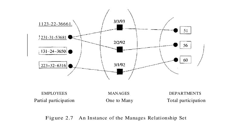
A relationship set like Manages is sometimes said to be one-to-many, to indicate that one employee can be associated with many departments (in the capacity of a manager), whereas each department can be associated with at most one employee as its manager. In contrast, the Works_In relationship set, in which an employee is allowed to work in several departments and a department is allowed to have several employees, is said to be many-to-many.
If we add the restriction that each employee can manage at most one department to the Manages relationship set, which would be indicated by adding an arrow from Employees to Manages in Figure 2.6, we have a one-to-one relationship set.
Participation Constraints
The key constraint on Manages tells us that a department has at most one manager. A natural question to ask is whether every department has a Manager. Let us say that every department is required to have a manager. This requirement is an example of a participation constraint; the participation of the entity set Departments in the relationship set Manages is said to be total. A participation that is not total is said to be partial.
Revisiting the Works_In relationship set, it is natural to expect that each employee works in at least one department and that each department has at least one employee. This means that the participation of both Employees and Departments in Works_In is total. The ER diagram in Figure 2.10 shows both the Manages and Works_In relationship sets and all the given constraints. If the participation of an entity set in a relationship set is total, the two are connected by a thick line; independently, the presence of an arrow indicates a key constraint. The instances of Works_In and Manages shown in Figures 2.3 and 2.7 satisfy all the constraints in Figure 2.10.

Weak Entities
Thus far, we have assumed that the attributes associated with an entity set include a key. This assumption does not always hold. For example, suppose that employees can purchase insurance policies to cover their dependents. We wish to record information about policies, including who is covered by each policy, but this information is really our only interest in the dependents of an employee. If an employee quits, any policy owned by the employee is terminated and we want to delete all the relevant policy and dependent information from the database.
We might choose to identify a dependent by name alone in this situation, since it is reasonable to expect that the dependents of a given employee have different names. Thus the attributes of the Dependents entity set might be pname and age. The attribute pname does not identify a dependent uniquely. Recall that the key for Employees is ssn; thus we might have two employees called Smethurst and each might have a son called Joe.
Dependents is an example of a weak entity set. A weak entity can be identified uniquely only by considering some of its attributes in conjunction with the primary key of another entity, which is called the identifying owner.
The following restrictions must hold:
- The owner entity set and the weak entity set must participate in a one-to-many relationship set (one owner entity is associated with one or more weak entities, but each weak entity has a single owner). This relationship set is called the identifying relationship set of the weak entity set.
- The weak entity set must have total participation in the identifying relationship set.
For example, a Dependents entity can be identified uniquely only if we take the key of the owning Employees entity and the pname of the Dependents entity. The set of attributes of a weak entity set that uniquely identify a weak entity for a given owner entity is called a partial key of the weak entity set. In our example, pname is a partial key for Dependents.
The Dependents weak entity set and its relationship to Employees is shown in Figure 2.1.1. The total participation of Dependents in Policy is indicated by linking them with a dark line. The arrow from Dependents to Policy indicates that each Dependents entity appears in at most one (indeed, exactly one, because of the participation constraint) Policy relationship. To underscore the fact that Dependents is a weak entity and Policy is its identifying relationship, we draw both with dark lines. To indicate that pname is a partial key for Dependents, we underline it using a broken line. This means that there may well be two dependents with the same pname value.

Class Hierarchies
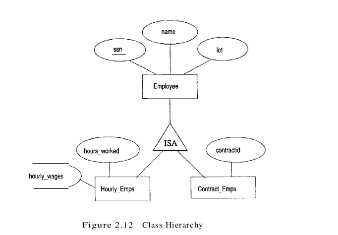
Sometimes it is natural to classify the entities in an entity set into subclasses. For example, we might want to talk about an Hourly_Emps entity set and a Contract_Emps entity set to distinguish the basis on which they are paid. We might have attributes hours_worked and hourly_wages defined for Hourly_Emps and an attribute contractid defined for Contract_Emps.
We want the semantics that every entity in one of these sets is also an Employees entity and, as such, must have all the attributes of Employees defined. Therefore, the attributes defined for an Hourly_Emps entity are the attributes for Employees plus Hourly_Emps. We say that the attributes for the entity set Employees are inherited by the entity set Hourly_Emps and that Hourly_Emps ISA (read is a) Employees. In addition and in contrast to class hierarchies in programming languages such as C++, there is a constraint on queries over instances of these entity sets: A query that asks for all Employees entities must consider all Hourly_Emps and Contract_Emps entities as well. Figure 2.12 illustrates,the class hierarchy.
A class hierarchy can be viewed in one of two ways:
- Employees is specialized into subclasses. Specialization is the process of identifying subsets of an entity set (the superclass) that share some distinguishing characteristic. Typically, the superclass is defined first, the subclasses are defined next, and subclass-specific attributes and relationship sets are then added.
- Hourly_Emps and Contract_Emps are generalized by Employees. As another example, two entity sets Motorboats and Cars may be generalized into an entity set Motor_Vehicles. Generalization consists of identifying some common characteristics of a collection of entity sets and creating a new entity set that contains entities possessing these common characteristics. Typically, the subclasses are defined first, the superclass is defined next, and any relationship sets that involve the superclass are then defined.
We can specify two kinds of constraints with respect to ISA hierarchies, namely, overlap and covering constraints. Overlap constraints determine whether two subclasses are allowed to contain the same entity. For example, can Attishoo be both an Hourly_Emps entity and a Contract_Emps entity? Intuitively, no. Can he be both a Contract_Emps entity and a Senior_Emps entity? Intuitively, yes. We denote this by writing ‘Contract_Emps OVERLAPS Senior_Emps’. In the absence of such a statement, we assume by default that entity sets are constrained to have no overlap. Covering constraints determine whether the entities in the subclasses collectively include all entities in the superclass. For example, does every Employees entity have to belong to one of its subclasses? Intuitively, no. Does every Motor_Vehicles entity have to be either a Motorboats entity or a Cars entity? Intuitively, yes; a characteristic property of generalization hierarchies is that every instance of a superclass is an instance of a subclass. vVe denote this by writing ‘Motorboats AND Cars COVER Motor_Vehicles.’ In the absence of such a statement, we assume by default that there is no covering constraint; we can have motor vehicles that are not motorboats or cars.
There are two basic reasons for identifying subclasses (by specialization or generalization) :
- We might want to add descriptive attributes that make sense only for the entities in a subclass. For example, hourly_wages does not make sense for a Contract_Emps entity, whose pay is determined by an individual contract.
- We might want to identify the set of entities that participate in some relationship. For example, we might wish to define the Manages relationship so that the participating entity sets are Senior_Emps and Departments, to ensure that only senior employees can be managers. As another example, Motorboats and Cars may have different descriptive attributes (say, tonnage and number of doors), but as Motor_Vehicles entities, they must be licensed. The licensing information can be captured by a Licensed_To relationship between Motor_Vehicles and an entity set called Owners.
Aggregation
As defined thus far, a relationship set is an association between entity sets. Sometimes, we have to model a relationship between a collection of entities and relationships. Suppose that we have an entity set called Projects and that each Projects entity is sponsored by one or more departments. The Sponsors relationship set captures this information. A department that sponsors a project might assign employees to monitor the sponsorship. Intuitively, Monitors should be a relationship set that associates a Sponsors relationship (rather than a Projects or Departments entity) with an Employees entity. However, we have defined relationships to associate two or more entities.
To define a relationship set such as Monitors, we introduce a new feature of the ER model, called aggregation. Aggregation allows us to indicate that a relationship set (identified through a dashed box) participates in another relationship set. This is illustrated in Figure 2.13, with a dashed box around Sponsors (and its participating entity sets) used to denote aggregation. This effectively allows us to treat Sponsors as an entity set for purposes of defining the Monitors relationship set.

When should we use aggregation? Intuitively, we use it when we need to express a relationship among relationships. But can we not express relationships involving other relationships without using aggregation? In our example, why not make Sponsors a ternary relationship? The answer is that there are really two distinct relationships, Sponsors and Monitors, each possibly with attributes of its own. For instance, the Monitors relationship has an attribute Until that records the date until when the employee is appointed as the sponsorship monitor. Compare this attribute with the attribute since of Sponsors, which is the date when the sponsorship took effect.
Conceptual Design with the ER Model
Developing an ER diagram presents several choices, including the following:
- Should a concept be modeled as an entity or an attribute?
- Should a concept be modeled an entity or a relationship?
- What are the relationship sets and their participating entity sets? Should we use binary or ternary relationships?
- Should we use aggregation?
Entity versus Attribute
While identifying the attributes of an entity set, it is sometimes not clear whether a property should be modeled as an attribute or as an entity set (and related to the first entity set using a relationship set). For example, consider adding address information to the Employees entity set. One option is to use an attribute address. This option is appropriate if we need to record only one address per employee, and it suffices to think of an address as a string. An alternative is to create an entity set called Addresses and to record associations between employees and addresses using a relationship (say, Has_Address). This more complex alternative is necessary in two situations:
- We have to record more than one address for an employee.
- We want to capture the structure of an address in our ER diagram. For example, we might break down an address into city, state, country, and Zip code, in addition to a string for street information. By representing an address as an entity with these attributes, we can support queries such as “Find all employees with an address in Madison, WI.”